|
|


 Arabic
 Bengali
 Chinese
 English
 French
 German
 Hebrew
 Hindi
Hindi Italian
 Japanese
 Korean
 Malay
Malay Polish
 Portuguese
 Spanish
 Turkish
 Ukrainian
 Vietnamese
|
ENCYCLOPEDIA OF RADIO ELECTRONICS AND ELECTRICAL ENGINEERING Intermittent power interruption device with long delay. Encyclopedia of radio electronics and electrical engineering
Encyclopedia of radio electronics and electrical engineering / Power Supplies A description is given of a simple device that allows, with a period of several hours, to automatically turn off and then turn on the power of any electrical appliance for a short time. The device is made on the ATtiny13A microcontroller and contains a minimum number of elements. An example of the use of such a device can be the periodic shutdown of a device to restart its program (this restores the functionality that was broken as a result of a failure). It is possible, for example, to interrogate an electronic thermometer or other sensor with a period of several hours and transmit its readings via a radio channel. In my village house, the recording system, in the absence of the owners, collects the readings of various sensors and sends them via a 3G modem to a specialized site where the database is stored. An unpredictable "drop-out" or even a complete cessation of updating information in the database was noticed. The reason was the loss of connection between the modem and the cellular network. Only a periodic reboot of all system devices (modem, router, controller) helped. I chose the easiest way to do this - turn off the power to the recording system for a few seconds every four or five hours. To implement this method, you need a pulse generator with a very long repetition period. The solution of the problem by the traditional method leads to a rather complex device with high requirements for the long-term stability of the elements. The alternative is an inexpensive device on a microcontroller. The principle of its operation can be as follows: the “sleeping” microcontroller periodically “wakes up” at the signal of the watchdog timer, checks how much time has passed since the last reboot of the system and, if the right moment has come, turns off its power for a while. The scheme of the device is shown in fig. 1. The +5V voltage is supplied from input socket XS1 (USB-BF) through normally closed contacts K1.1 of relay K1 to output sockets XS2 and XS3 (dual USBA-2J). With the output PB4 of the microcontroller DD1, an electronic key on the transistor VT1 is connected, in the collector circuit of which the winding of the relay K1 with a resistance of 75 ohms is connected (the operating voltage of the winding is 5 V).
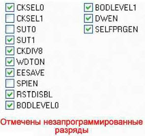
The HL1 LED serves as an indicator of the device status. It lights up when power is off from sockets XS2 and XS3. On power-up, the microcontroller configures all of its port lines as inputs, so the transistor remains off and the relay coil is de-energized. The microcontroller program was developed in the Algorithm Builder for AVR environment. The block diagram of the algorithm of its work is shown in fig. 2. The ATtiny13A microcontroller configuration bit states required for the program to work are shown in fig. 3.
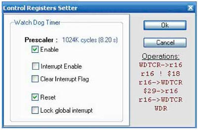
The operating mode of the watchdog timer of the microcontroller should be set in the development environment, as shown in fig. 4, which corresponds to the longest exposure time - 8,2 s. The program is built so that most of the time the microcontroller is in "sleep" mode. "Waking up" when the watchdog timer is triggered, it, according to the program, checks the contents of the register R0 and increases its contents by one.
The value stored in the R0 register does not change in the "sleep" mode, which allows using its register as a counter for the number of "wake-ups" of the microcontroller. Register overflow occurs approximately every 35 minutes (8,2 s x 256). If its contents are non-zero, the counter overflow has not yet occurred and the microcontroller "falls asleep" again (it switches to Power down mode). Overflows of register R0 are counted by the program in register R1. In my case, eight overflows were enough (8,2s x 256 x 8 = 4,7 hours), so the initial value in register R1 is 7, and each overflow of register R0 reduces it by one. After the specified time interval, the program configures the PB4 pin as an output and sets it to a high logic level. This opens the transistor VT1 and leads to the operation of the relay K1, which breaks the power circuit of the devices connected to the XS2 and XS3 connectors. After 8,2 s, the watchdog timer fires again, and the program returns the PB4 output to the input mode, which turns off the K1 relay. Power to external devices is restored. As a result, approximately once every four and a half hours, the device de-energizes the device, which is fed through it with a voltage of 5 V, for eight seconds. The interrupter is mounted on a fragment of a breadboard with dimensions of 20x50 mm. The microcontroller DD1 is installed in the panel. Relay K1 - SRS-05VDC-SL. Checking the manufactured breaker should be started without a microcontroller. A voltage of 5 V applied to socket XS1 must be present at socket 8 of the microcontroller panel and at the left (according to the diagram) output of the relay winding K1. This voltage is measured relative to socket 4 of the microcontroller board. You can check the operation of the transistor VT1 and relay K1 by short-circuiting slots 8 and 3 of the microcontroller panel - the relay should work, and the LED should turn on for the duration of the circuit. After installing the microcontroller in the panel, checking the operation of the device consists in a long wait for the moment when the LED turns on and the relay operates. A heat-shrinkable tube is put on a tested board with parts, through which the glow of the HL1 LED is clearly visible. The finished breaker is shown in Fig. 5.
It is interesting to note the "side effect". In order not to wait too long for the relay to operate during the check, a somewhat simplified program (without analyzing the state of the register R1) was loaded into the microcontroller of the receiving part of the device described in my article "Radio-controlled network extension cable" ("Radio", 2014, No. 7, p. 31 -33). During its operation, every 35 minutes, the extension sockets were turned on for 8 seconds. On New Year's Eve, Christmas tree illumination was connected to this extension cord. The effect was unexpected: at the most inopportune time, the illumination suddenly turned on. The Christmas tree, blinking merrily, cheered up those around for a few seconds. Life has shown that a completely useless, at first glance, device, having worked in a village house for more than a year, turned out to be ... useful. When analyzing the information registered on the site, it became clear how rebooting the system solves the problem of freezing the cellular channel. At the same time, to fix the failure, you did not have to go to the site to restart the system. The device turned out to be compact and convenient. It should also be noted that it has a low current consumption in standby mode, which makes it possible to apply such a solution in self-powered systems. The principles underlying the considered algorithm can also be used for other purposes, for example, to simulate the presence in the house. The microcontroller program can be downloaded from ftp://ftp.radio.ru/pub/2016/08/pr.zip. Author: A. Pakhomov
Machine for thinning flowers in gardens
02.05.2024 Advanced Infrared Microscope
02.05.2024 Air trap for insects
01.05.2024
▪ Gardening is one of the best antidepressants ▪ Mutual understanding between human friends ▪ Let's charge the battery with our feet and hands ▪ The value of dark chocolate for older people with diseased arteries
▪ section of the site for the radio amateur-designer. Article selection ▪ article What to do? Popular expression ▪ article Where do people of the Caucasian race live? Detailed answer ▪ article Hunting knot. Travel Tips ▪ article Disappearing coins. Focus Secret
Home page | Library | Articles | Website map | Site Reviews
www.diagram.com.ua |


 Leave your comment on this article: