|
|


 Arabic
 Bengali
 Chinese
 English
 French
 German
 Hebrew
 Hindi
Hindi Italian
 Japanese
 Korean
 Malay
Malay Polish
 Portuguese
 Spanish
 Turkish
 Ukrainian
 Vietnamese
|
ENCYCLOPEDIA OF RADIO ELECTRONICS AND ELECTRICAL ENGINEERING Voltage converter on the microcontroller to power the measuring device. Encyclopedia of radio electronics and electrical engineering
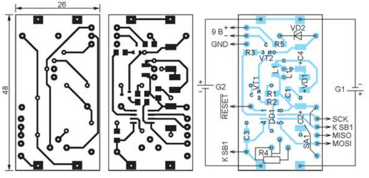
Encyclopedia of radio electronics and electrical engineering / Voltage converters, rectifiers, inverters The proposed device is a 3 V DC to 9 V DC converter. It is made in the dimensions of a nine-volt Krona battery and is intended to replace it in self-powered measuring instruments. Primary voltage source - two salt or alkaline galvanic cells of size AAA. It is possible to use Ni-MH batteries of the same size. Converter efficiency - 66...81%. The converter circuit is shown in fig. 1. Its main component is an ATtiny13A-SU (DD1) microcontroller clocked by an internal RC oscillator. The step-up voltage converter is implemented on a transistor VT1, an inductor L1, a Schottky diode VD1 and a capacitor C4. Transistor VT2 disconnects the load from the converter in the "sleep" mode of the microcontroller. Zener diode VD2 and resistor R5 protect the elements of the converter in the event of an interruption (shutdown) of the load. In normal operation, there is no current through the protective circuit.
The converter is designed to operate on a constant load. Its output voltage is not stabilized and depends on the supply voltage. For example, it drops to 7,6 V when the supply drops to 2,5 V. For a more complete use of the energy of the primary power source and maintaining the output voltage at a given level, the DD1 microcontroller, when starting the converter, checks the voltage at its output. To do this, part of the output voltage from the trimmer resistor R4 is fed to the input PB4 of the microcontroller, which operates in the input mode of the built-in voltage comparator. All components of the transducer are placed on a 48x26 mm board made of 1 mm thick fiberglass laminated on both sides. Its drawing and arrangement of parts are shown in Fig. 2. On the side of the board, free from parts, four contacts for connecting batteries are soldered into the holes intended for them. The contacts are cut from 0,3 mm thick brass sheet. The height of the contact is 10 mm, the width is 5...8 mm, the length of the petal for soldering into the hole is 2 mm, the width is 1,5 mm.
Oxide capacitors are TECAP size D, other capacitors and resistors are size 1206 for surface mounting. Trimmer resistor R4 - SP3-19a-0,5 W, inductor L1 - LQH43CN101K. The choice of inductor significantly affects the efficiency of the converter. For example, replacing the choke mentioned above with a slightly larger RLB0712 increases the efficiency by 3 ... 5%, but, unfortunately, the dimensions of the converter go beyond the dimensions of the Krona battery. To mount this inductor on the board, contact pads with holes are provided, marked L1'. It is mounted in a "lying" position. Replacing the BAT1 diode originally used in one of the converter options as VD41 with an MBR0540 made it possible to increase the efficiency by 2%. A view of the assembled transducer from the parts side is shown in fig. 3, and from the side of the installation of batteries - in fig. 4.
Rice. Fig. 4. View of the assembled converter from the side where the batteries are installed The microcontroller program uses its eight-bit fast PWM timer and analog comparator. The pulse repetition frequency with PWM is chosen equal to 37500 Hz - the maximum possible at a microcontroller clock frequency of 9,6 MHz. An internal reference voltage source is connected to the non-inverting input AI N0 of the analog comparator. Table
1 - not programmed
The controlled output voltage supplied to the PB4 pin of the microcontroller is fed to the inverting input of the AIN1 comparator through the ADC multiplexer. The output status of the ACO comparator is checked by the timer overflow interrupt handler T0. When ACO=1, there is an increment of the value in the timer comparison register, which increases the duty cycle of the pulses that control the transistor VT1 of the converter. With ACO=0, this value remains unchanged because the output voltage has already reached the set 9V. The converter off timer is implemented in software and is a counter decremented by interrupts from the timer T0. The initial value written to the registers of this counter is calculated by the program using the formula N=Toff37500, where Toff - the required duration of the converter before shutdown, s; 37500 - control pulse repetition frequency, Hz. The program is given Toff=900 s (15 min). After this time, the microcontroller "falls asleep", switching to the POWER DOWN micropower consumption mode. It is possible to control the converter using the optional button SB1, the connection of which is shown in the diagram in fig. 1 with dashed lines. An external interrupt request, generated by pressing this button, returns the "sleep" microcontroller to the operating mode. And if you click on it while the converter is running, the microcontroller will switch from working to "sleep" mode, turning off the converter. To operate the button in various modes, the program generates delays with a duration of 0,5 s. In the "sleep" mode of the microcontroller, the converter consumes only 6 ... 10 μA, therefore, if there is a button in the SA1 switch, there is no need and it can be omitted by replacing it with a jumper. If the SB1 button is missing, then after the shutdown timer has expired, switching on the converter with the SA1 switch is possible only after two minutes. During this time, with the switch open, the microcontroller consumes the energy stored in capacitor C2 and is in "sleep" mode. The converter is designed without being tied to a specific type of measuring device that requires a supply voltage of 9 V. Modification of such a device comes down to installing an SA1 switch or an SB1 button in it. For convenience, they can be connected to the converter using miniature connectors. The reverse replacement of the converter with the Krona battery does not cause difficulties. After mounting all the parts on the board, except for the L1 inductor and checking it for open and short circuits, set the R4 resistor slider to the middle position and proceed to programming the microcontroller. The codes from the CONVERTER-DC2.hex file attached to the article must be loaded into the microcontroller program memory. Its configuration must be programmed according to the table. Please note that the CKDIV8 bit programmed by the microcontroller manufacturer must be deprogrammed. All pads necessary for connection with the programmer are available on the board. If the programmer works only with a supply voltage of 5 V, apply the same voltage to the power supply circuit of the microcontroller. A voltage of 3 V will need to be supplied to the board after successful programming. Measure the current drawn by the meter with which the converter is to be used, and load the converter with a suitable resistance resistor. After installing the inductor L1 in place, apply power to the converter and adjust the output voltage with a tuning resistor R4, making it equal to 9 V. Moving the trimming resistor slider to its lower output according to the circuit increases the output voltage, and decreases it in the opposite direction. Please note that the program changes the output voltage only when the power is turned on or when the microcontroller wakes up from sleep mode. Switch off the inverter, connect a real load to it and switch it on again. If the voltage differs from the required, correct it with a trimming resistor R4. Then measure the current drawn from G1 and G2 and calculate the converter efficiency. For one of the samples I made, it turned out to be 74% at a supply voltage of 3 V and 64% at 2 V. With a converter in which the RLB0712 choke is installed, an efficiency of 78% and 66%, respectively, was obtained. If, with an input voltage of 3 V and a load current of 6 mA, the output voltage is set to 9,2 V, then with an input voltage of 2 V, it will decrease to 8,5 V. With further discharge of the supply battery, when the output voltage drops to 6,5 V, the low battery symbol appears on the indicator of the measuring device. I made two copies of the converter: one for powering the DT930F+ multimeter, and the second for the MY6243 capacitance and inductance meter. These devices do not have a sleep timer, so it was not uncommon to completely drain their batteries due to forgetfulness. After installing converters in them, such troubles stopped. The microcontroller program can be downloaded from ftp://ftp.radio.ru/pub/2017/01/conv.zip. Author: N. Salimov
Machine for thinning flowers in gardens
02.05.2024 Advanced Infrared Microscope
02.05.2024 Air trap for insects
01.05.2024
▪ Now I understand why we need an appendix ▪ Subminiature Digital Camera CardCam ▪ Plastic for household recycling ▪ Holidays threaten childhood obesity
▪ section of the site Note to the student. Article selection ▪ article Humiliated and Insulted. Popular expression ▪ article Who got the oil first? Detailed answer ▪ article Installer of steel and reinforced concrete bridges. Standard instruction on labor protection ▪ article Funny fan. Focus Secret
Home page | Library | Articles | Website map | Site Reviews
www.diagram.com.ua |


 Leave your comment on this article: