|
|


 Arabic
 Bengali
 Chinese
 English
 French
 German
 Hebrew
 Hindi
Hindi Italian
 Japanese
 Korean
 Malay
Malay Polish
 Portuguese
 Spanish
 Turkish
 Ukrainian
 Vietnamese
|
ENCYCLOPEDIA OF RADIO ELECTRONICS AND ELECTRICAL ENGINEERING Power supply of the electromagnetic relay with reduced voltage. Encyclopedia of radio electronics and electrical engineering
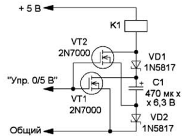
Encyclopedia of radio electronics and electrical engineering / Power Supplies The supply voltage of amateur radio devices has been getting smaller and smaller over the years. In addition, various devices based on microcontrollers and digital microcircuits have become widespread, the supply voltage of which is also steadily decreasing, and the voltage of 5 V already seems to be large. But building devices with such a supply voltage sometimes leads to difficulties. In particular, if it is necessary to switch the mains voltage, in some cases it is advisable to use an electromagnetic relay. But relays with a nominal voltage of 3 ... 5 V are much less common than with a voltage of 12 V. At the same time, it is known that the current (and, accordingly, the voltage) at which the relay releases is several times less than the operating current (voltage). In addition, relays in most cases reliably operate at a voltage of 20 ... 40% less than the nominal one. To put the question a little differently, then you need to make the relay operate at a reduced voltage, at which it will reliably hold the contacts in a closed (or open) state. In addition, supplying the relay with reduced voltage significantly increases the efficiency of the entire device. There are many schemes of devices that provide relay operation at low voltage in various printed sources [1, 2], including patented ones [3], as well as on the Internet [4, 5]. Similar devices are also used to reduce the response time of the relay when powered by their rated voltage [6]. The principle of operation of most of these devices is based on the fact that they use a storage capacitor, which, at the time of switching, is connected in series with the power source, as a result of which the total voltage doubles and the relay reliably operates. After the capacitor is discharged, the relay is powered by about half the voltage, respectively, consuming less current. A diagram of another version of such a device is shown in Fig. 1. Using it, you can power the relay with a voltage approximately half the nominal voltage, or, at the rated supply voltage, turn on not one, but two relays in series. Field-effect transistors are used for switching here, therefore, a low-power unit (microcontroller, logic chip, etc.) can be used as a control signal source, which does not provide the current required for switching the relay. After applying the supply voltage through the relay winding and diodes, the capacitor C1 is charged almost to the supply voltage. This happens quickly, since the resistance of the relay winding is usually small. The relay itself, as a rule, does not work. After the control signal is applied, both transistors open. In this case, the positive terminal of the capacitor C1 is connected to a common wire, and the negative terminal is connected to the relay winding. A voltage of about 10 V will be applied to the winding, and the relay will operate. After the capacitor is discharged, the relay will be powered by a voltage slightly less than 5 V.
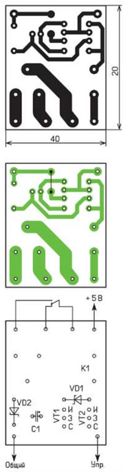
As an example, the MZP A 001 46 relay was tested. According to its passport, the minimum supply voltage is 8,99, the maximum is 22,5 V, its one changeover contact is designed for switching loads with mains power, the winding resistance is 450 Ohm. Real measurements showed that this relay operates at a voltage of about 6,5 V, and releases at 1,5 V. The capacity of the capacitor must be sufficient to operate the relay. According to the passport, the response time of the specified relay at the rated supply voltage is no more than 10 ms, and the time constant of the relay winding together with the capacitor is about 200 ms. This will ensure its reliable operation. A diode, which is usually installed in parallel with the relay coil, which protects the switching element (in this case, a field effect transistor) from self-induction EMF when the current through the winding stops, is not needed in this case. When the transistors close, the resulting current in the winding through the diodes will charge the capacitor. Schottky diodes are used, since the drop on them is less than on ordinary silicon ones. All elements can be placed on the board of the main device or on a separate one-sided board, the drawing of which is shown in fig. 2, and the appearance - in Fig. 3. In this device, the relay worked confidently when the voltage dropped to 4,2 V.
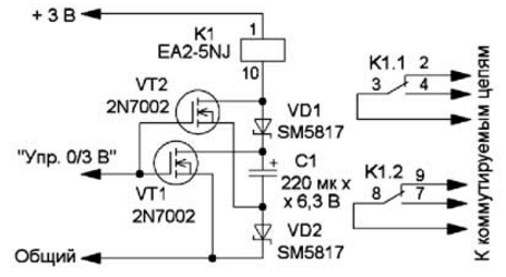
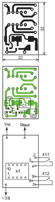
If the supply voltage of the main device is 3 ... 3,3 V, a relay with a rated voltage of 5 V can be used together with it. the maximum switched alternating voltage is 2 V. The relay worked at a voltage of 5 V, and released at 180 V. If you use elements for surface mounting (Fig. 4), the dimensions of the device will differ slightly from the overall dimensions of the relay. For the elements indicated in the diagram (capacitor - tantalum for surface mounting, size D). A possible drawing of the printed circuit board is shown in fig. 5. In this device, the relay worked reliably at a supply voltage of 2,5 V. In the device, it is desirable to use transistors with an opening voltage of not more than 1,5 ... 2 V. But it should be noted that the feature of this relay is J a certain polarity of the supply voltage supplied to the winding. If it is not followed, the relay will not work.
We should also not forget about the protection of field-effect transistors from breakdown by static electricity. To do this, for the period of transportation or storage, the input is connected to a common wire with a piece of bare wire. And, of course, you must first check at what voltages the relay operates and releases. In addition, at a lower voltage (near the release voltage), the force applied to the relay contacts decreases, which can lead to an increase in the contact resistance of the contact group. Literature
Author: I. Nechaev
Machine for thinning flowers in gardens
02.05.2024 Advanced Infrared Microscope
02.05.2024 Air trap for insects
01.05.2024
▪ Budget tracker with Bluetooth for monitoring children ▪ High resolution fluorescence microscopy
▪ section of the site Amateur Radio Technologies. Selection of articles ▪ article by Nibelmez. Popular expression ▪ article Where did the blue and yellow colors of the Ukrainian flag come from? Detailed answer ▪ Tongariro article. Nature miracle
Home page | Library | Articles | Website map | Site Reviews
www.diagram.com.ua |


 Leave your comment on this article: