|
|


 Arabic
 Bengali
 Chinese
 English
 French
 German
 Hebrew
 Hindi
Hindi Italian
 Japanese
 Korean
 Malay
Malay Polish
 Portuguese
 Spanish
 Turkish
 Ukrainian
 Vietnamese
|
ENCYCLOPEDIA OF RADIO ELECTRONICS AND ELECTRICAL ENGINEERING Without a straightener, it's like without hands. Encyclopedia of radio electronics and electrical engineering
Encyclopedia of radio electronics and electrical engineering / Voltage converters, rectifiers, inverters To get started, answer a simple question: "What is the voltage in the network?" Surely most will say; "220 volt". Others will add: "Variable, 50 hertz." All this is, of course, true. The voltage (effective) in most lighting networks is 220 V, and it is variable, sinusoidal, and the frequency of the sinusoidal oscillations is 50 Hz, which corresponds to a repetition period of 20 milliseconds.
But few people know that the amplitude value of the voltage in the network is approximately 310 V, and the difference (range) between the maximum and minimum values is as much as 620 V (Fig. 1, a). It is not difficult to calculate the amplitude value - you need to multiply the effective voltage by √2. What does it give? Thus, it is possible to calculate what kind of direct voltage will be obtained from an alternating one if it is rectified. This is done using semiconductor diodes (Fig. 2, a). The diode (it is designated by the symbol VD1) has two electrodes - the cathode (k) and the anode (a). The current through the diode can only pass in the direction from the anode to the cathode (along the "arrow" of its graphic image). On the reverse side, the current through the diode (especially if it is silicon) almost does not flow - they say that then the diode is "closed".
In order for the rectification to be the most perfect - full-wave, four (VD1 - VD4) diodes are combined into a so-called bridge circuit (Fig. 2, b). But there are also ready-made diode bridges - in fig. 2, one of them is shown - VD1. A two-wave bridge rectifier works like this. Imagine a conventional HL1 incandescent lamp for a voltage of 220 V. Then, according to the diagram in Fig. 3, and it will shine in much the same way as if there were no diodes VD1 - VD4 at all. After all, when the voltage polarity shown in Fig. 10b, the current will flow through the VD3 diode, the HL1 lamp and the VD1 diode. When, during the other 4 ms, the polarity of the voltage in the network changes to the opposite (Fig. 10, c), the current will flow through VD3, the HL3 pump and the VD1 diode. In other words, now the current through the lamp HL2 all the time goes in the same direction, and not in different directions, as in Fig. 1 in the AC tone network. But for an incandescent lamp, this seems to be indifferent - its filament heats up the same way, no matter which direction the current goes. Heating will be the same, we will apply voltage to the lamp according to the graph in Fig. 1,a (alternating voltage with a frequency of 1 Hz) or according to the graph in fig. 50b (pulsating voltage with a frequency of 1 Hz).
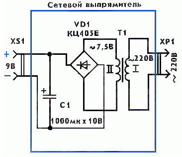
If, however, an oxide (electrolytic) capacitor C1 is now connected in parallel with the lamp (in Fig. 3, d), the HL1 lamp will flash much brighter. After all, the supply of electricity in the capacitor C1 is almost enough to compensate for the decrease in voltage in the "intermissions" between individual ripples. Consequently, the voltage across the capacitor C1 will be close to the amplitude value of 310 V (Fig. 1, c). In the course of such an experiment, our light bulb may well simply burn out! We will assume that our experiment is purely speculative - it is unlikely that you will need such a high voltage (310 V!), Which, meanwhile, was popular in lamp technology. Now transistor and microcircuit technology deals with voltages less than 10...50 times. Yes, this is good - this level is already quite safe. Let's reduce the voltage in the usual way - using a step-down transformer T1 (Fig. 4). It can be incandescent from an old tube TV. If 220 V is applied to the primary winding I, then the voltage on the secondary winding II will be up to about 7,5 V. We already know that this is the effective voltage value. This means that the amplitude value should seem to be 1,41 times larger, and will be approximately 10,5 V. But on the capacitor C1 it will actually be somewhat less, namely, about 9 V. The fact is that so far we conditionally did not take into account the voltage drop across the two "open" diodes. And it is neither more nor less - approximately 1,4 V (for silicon diodes). Consequently, in reality we will get a constant voltage of about 9 V. And our mains rectifier will be able to play the role of Krona, Korund, Oreol-1 batteries or a 7D-0, 115-U1.1 battery. From such a rectifier it is quite possible to power a small receiver, a small player ...
To connect to the mains, the rectifier uses a conventional XP1 plug (Fig. 4). The equipment is connected to it using an XS1 socket, which is taken from an old Krona battery. The oxide capacitor C1 can be of any type: the larger its capacitance, the better, there will be less ripple of the rectified voltage. Diode bridge VD1 is taken with any letter index from diode assemblies of the KTs405, KTs402 series. If there is no finished assembly, it is replaced by a bridge assembled from four diodes. The most suitable diodes for such a replacement are the KD105 or KD208, KD209 series. But you can also use the modern KD226 series or use the D226 series diodes that were popular in the past. If you take not silicon, but germanium diodes, then the rectified voltage will increase to almost 10 V, which, however, is quite acceptable for equipment. The resulting "additive" is explained by the fact that the forward voltage drop of germanium diodes is less (about 0,4 V for each diode) than that of silicon ones (about 0,7 V). Such diodes, quite possibly, were "strewn" by avid radio amateurs, and they will share them. The old diodes of the D7 series (for example, D7Zh, D7E) will work very well. But more ancient ones are also suitable - DGC-24, DGC-25, DGC-26, DGC-27. Do not forget to check the diodes for serviceability before assembling, this is especially important if you got them by accident. You can check them in different ways, but it is best to do this with an ohmmeter. In one direction, the diode (especially if it is germanium) will have a very small resistance, and in the other direction, on the contrary, it will be very large (if it is silicon). Author: V.Vasiliev
Machine for thinning flowers in gardens
02.05.2024 Advanced Infrared Microscope
02.05.2024 Air trap for insects
01.05.2024
▪ The Greenland ice sheet is melting catastrophically ▪ The military donated two space telescopes to NASA ▪ battery life extension gadget ▪ LG KiZON - a wearable electronic device for a child
▪ section of the site Voltage stabilizers. Article selection ▪ article How drunk Zyuzya. Popular expression ▪ article Where is Ismail Somoni Peak located? Detailed answer ▪ article Glass cutter. Standard instruction on labor protection ▪ article Simple car security devices. Encyclopedia of radio electronics and electrical engineering ▪ article Banknotes from nowhere. Focus Secret
Home page | Library | Articles | Website map | Site Reviews
www.diagram.com.ua |


 Leave your comment on this article: