|
|


 Arabic
 Bengali
 Chinese
 English
 French
 German
 Hebrew
 Hindi
Hindi Italian
 Japanese
 Korean
 Malay
Malay Polish
 Portuguese
 Spanish
 Turkish
 Ukrainian
 Vietnamese
|
ENCYCLOPEDIA OF RADIO ELECTRONICS AND ELECTRICAL ENGINEERING Welding transformer: calculation and manufacturing
Encyclopedia of radio electronics and electrical engineering / welding equipment Electric arc welding is the most common method of permanent connection of metal parts in industry and in everyday life. Appearing 120 years ago, due to its high manufacturability, it quickly and almost everywhere replaced other welding methods. Today, an electric arc welding machine is an indispensable part of the equipment of a home workshop or a dream of its owner. The article describes how to calculate and manufacture a welding transformer, and provides the necessary information for the competent design and manufacture of such a device as a whole. The electric arc was discovered in 1802 by Vasily Vladimirovich Petrov, professor of physics at the St. Petersburg Medical and Surgical Academy. Describing this phenomenon in 1803, V. V. Petrov pointed out the possibility of its practical application both for lighting and for melting metals. But only 80 years later, in 1882, the talented Russian inventor Nikolai Nikolaevich Benardos managed to develop an industrially suitable method for electric arc welding of metals. According to the Benardos method (Fig. 1), a welding seam 4 is formed by melting a filler metal rod 3 in an electric arc 1 burning between a carbon or tungsten electrode 2 and the parts to be joined 5.
Somewhat later, in 1888, Nikolai Gavrilovich Slavyanov developed a different welding method (Fig. 2). In this case, the electric arc burns between the connected parts 5 and the electrode, from the molten metal of the core 2 of which a seam 4 is formed. The gases released during combustion and evaporation of the material of the protective coating (coating) 3 of the electrode protect the melt from oxidation and make the arc more stable. The first designs of coated welding electrodes were created by N. N. Benardos. The modern look was given to them by the Swedish engineer Kelberg in 1911.
Due to its simplicity and manufacturability, it is this method of manual welding, sometimes abbreviated as MMA, that has become most widespread. Welding is carried out both with direct and alternating current, and in the first case, two options are possible: with the plus of the welding current source connected to the product (direct polarity) or to the welding electrode (reverse polarity). The polarity for which the welding electrode is designed must be indicated in its passport data. Most often, the reverse is used. The idea of submerged arc welding also belongs to N. G. Slavyanov. However, the American firm "Linde" received a patent for the method of welding steel under a layer of powdered substances that melt during welding only in 1936. In the USSR, a similar technology was developed and introduced into production in 1938-1940. Institute of Electric Welding of the Academy of Sciences of the Ukrainian SSR (now named after Evgeny Oskarovich Paton). It was this method that made it possible to establish the mass production of armored vehicles during the Great Patriotic War. During the Second World War in the United States, automated welding of metals in an argon or helium jet using a non-consumable tungsten (TIG) and consumable (MIG) electrode was developed. The latter option is shown schematically in Fig. 3. The arc 6 burns between the parts to be welded 1 and the wire 2, which, as it melts, is fed to the place of welding with the help of rolls 3 along the guide 4. The inert gas entering through the nozzle 5 envelops the welding zone and protects the molten weld metal 7 from oxidation.
In 1952, K. V. Lyubavsky and N. M. Novozhilov invented an alloyed electrode wire of a special composition, the use of which makes it possible to weld with a consumable electrode in a carbon dioxide environment. It is this method (the abbreviation MAG has been assigned to it) that has found wide application in the car service today. Having gained some understanding of the methods of electric arc welding, let's get acquainted with the properties of an electric arc - a powerful long-term electric discharge between electrodes that are energized in an ionized gas environment. The process of its occurrence begins with the approach and contact of two electrodes - the anode and the cathode, one of which in this case is the workpiece being welded. Then the electrodes are moved apart and a spark jumps between them at the moment of opening the electrical circuit, ionizing the gas in the interelectrode space. If a voltage sufficiently high for the electrical breakdown of the gas gap is briefly applied to the electrodes, it is possible to ionize the gas even without a primary short circuit. In the "conduction channel" formed due to the initial ionization, electrons move from the cathode to the anode under the action of an electric field, developing a significant speed. Colliding with neutral gas atoms, they knock out new electrons from them, thereby supporting ionization. This is accompanied by the release of a large amount of heat. As a result, the substance in the arc column, heated to 5000...7000°C, passes into the plasma state. The electrons that reach the anode give it their energy. Here a strongly heated "anode spot" is formed. Positive plasma ions move towards the cathode and, giving it energy, form the so-called "cathode spot". Usually, the electronic component of the current predominates in the arc, as a result of which more heat is generated at the anode than at the cathode. It is believed that the anode accounts for 43%, and the cathode - 36% of the energy, the rest is dissipated in the arc column. A necessary condition for the existence of an arc is the high temperature of the cathode maintained by ion bombardment, due to which the emission of electrons occurs, which ionizes the gas in the arc column. On fig. 4 (curve 1) shows a typical static current-voltage characteristic of an electric arc [1] for a welding electrode with a diameter of 3 mm (a cross section of approximately 7 mm2).
On the characteristic, descending (current density in the electrode is less than 12 A / mm2), horizontal and ascending (current density - more than 80 A / mm2) sections are distinguished. When welding with direct current, the point of intersection of this curve with the load characteristic of the power source (curve 2) must be in a horizontal section. The voltage UD falling on the arc mainly depends on the gas composition of the medium and very weakly on the welding current lCB. With an accuracy sufficient for practical application, it is calculated by the empirical formula Ud \u0,05d Ur + 18 Isv, where Ur \u14d 11 V for air, XNUMX V for carbon dioxide and XNUMX V for a mixture of the latter with argon. If the arc is included in the low (industrial) frequency alternating current circuit, the operating point moves continuously along the downward and horizontal sections of the characteristic. Since the current stops at the end of each half cycle, the arc is extinguished. However, in the next half-cycle, due to the thermal emission of electrons from the metal sections that did not have time to cool down and the residual ionization of the gas gap that persists for some time, the arc reappears as soon as the voltage between the electrodes reaches a value called the ignition voltage. To achieve stable burning of the AC arc, certain measures are necessary. For example, special electrodes are used, in the composition of the coating of which substances with a low ionization potential are added. Arc stability improves with increasing open-circuit voltage of the welding source (it is measured with the load turned off). However, this parameter is limited by the safety requirements of service personnel and, according to GOST 95-77E, should not exceed 80 V. The generally accepted way to obtain a stable arc at a relatively low open-circuit voltage of the power source is to connect an inductive reactance in series with the welding circuit. The result is a phase shift between current and voltage. The zero instantaneous value of the current at which the arc goes out corresponds to the maximum voltage that ignites it again. In this case, a source with an open circuit voltage of 60 ... 65 V is sufficient. In addition, by changing the inductance, you can adjust the welding current. The metal of the electrode melted by the electric arc enters in drops [2] into the pool of liquid metal formed on the surface of the workpiece to be welded at the base of the arc (this place is usually called a crater). The process begins with the formation of a layer of molten metal at the end of the electrode. As the metal accumulates, it collects into a drop, which, in the end, bridges the arc gap. At this moment, a short circuit of the welding circuit occurs, accompanied by a sharp increase in current. The resulting electromagnetic forces break the drop, and a new arc appears between it and the end of the electrode. The drop falls with acceleration into the crater, and part of the metal in the form of splashes is ejected from the welding zone. The reason for the appearance of an excessively large number of frozen metal drops around the seam, which can only be removed with a hammer and chisel, often lies in the form of the load characteristic of the welding power source (dependence of its output voltage on the load current). For manual welding, such a characteristic is necessary so that the short-circuit current |kz exceeds the rated welding current Icv by no more than two times [3]. Unlike manual, semi-automatic welding in a shielding gas environment is carried out with a higher current density corresponding to the beginning of the ascending section of the static current-voltage characteristic of the arc. For self-regulation of the welding process, a rigid load characteristic is required here (curve 3 in Fig. 4). In non-professional manual electric welding, alternating current sources are mainly used. This is due to the simplicity and cheapness of the latter, although the quality of the weld is inferior to that achievable with direct current. Even 10 - 15 years ago, the industry practically did not produce household devices for electric arc welding. Now the situation has changed, there are quite a few devices on the market that are quite suitable in terms of parameters for domestic use. But their price is still beyond the reach of very many. Therefore, amateur designers, as before, are trying to make this miracle of technology with their own hands. Many of them, having some practical skills in manual welding, have no idea about the requirements for a welding power source. As a result, an apparatus made "by eye" from improvised materials does not provide the required quality of the weld and is unsafe in operation. The main assembly of the AC welding source is a special, as a rule, single-phase welding transformer. With its help, the mains voltage is reduced to the value necessary for welding and at the same time isolates the welding circuit from the mains. The equivalent circuit of the transformer [4] used in the calculations is shown in fig. 5.
The transformation ratio n is the ratio of the number of turns of the windings w1/w2 (hereinafter, indices 1 and 2 refer to the primary and secondary windings, respectively); U1, U2 - voltages on the windings; r1, r2 - their active resistances; Rm - loss resistance in the magnetic circuit; Lm is the magnetization inductance associated with the magnetic flux common to the windings; L1s, L2s - leakage inductances arising from the fact that part of the magnetic flux of each of the windings dissipates in space without interacting with the other winding. Using the equivalent circuit, it is possible to evaluate the influence of certain parameters of the transformer on such important quantities as open-circuit voltage and short-circuit current. According to the configuration of the magnetic circuit, armored transformers (Fig. 6, a) with windings placed on the central core, and rod transformers (Fig. 6, b) with windings on one or two cores are distinguished. Rod-type transformers are characterized by increased efficiency and better winding cooling conditions. The latter makes it possible, by setting an increased current density, to reduce the consumption of the winding wire. Therefore, welding transformers, with rare exceptions, are made rod-type. The magnetic circuit is usually recruited from sheet electrical (transformer) steel with a thickness of 0,35 ... 0,5 mm.
The windings of transformers are cylindrical and disk. Cylindrical (Fig. 7, a) are wound one on top of the other. The distance between them is minimal, and almost the entire magnetic flux of the primary winding interacts with the secondary. Therefore, the leakage inductances L1s and L2s are small, the short-circuit current is limited only by the active resistance of the windings and is many times greater than the operating one. As mentioned earlier, a transformer with such a load characteristic is not suitable for manual welding. It must be supplemented with a ballast resistor (rheostat) or a choke.
These elements greatly increase the dimensions and weight of the welding source, and the inevitable energy losses in them reduce its efficiency. In transformers with disk windings (Fig. 7, b), a significant part of the magnetic flux of the primary winding bypasses the secondary. As a result, the leakage inductances L1s and L2s connected in series in the welding circuit are larger than in the previous case, and their reactance significantly affects the short-circuit current of the secondary winding. As already noted, the presence of inductance in the welding circuit is also favorable for stable arc burning. Therefore, disc-wound transformers are best suited for manual AC welding. Sometimes their windings are made movable and, by changing the distance between them, they regulate the leakage inductance, and with it the welding current. The specificity of the welding transformer is that its load is not constant. It is usually considered that the share of the time of work under load in a cycle consisting of the actual welding and a pause does not exceed 60%. For household welding transformers, an even smaller value is often taken - 20%, which allows, without a significant deterioration in the thermal regime, to increase the current density in the transformer windings and reduce the window area of \u150b\u8bits magnetic circuit necessary to accommodate the windings. At a welding current of up to 2 A, the current density in the copper winding is considered to be 5 A/mm2, in aluminum - 5 A/mmXNUMX [XNUMX]. For a given power, the dimensions and weight of the transformer will be minimal if the induction in its magnetic circuit reaches the maximum allowable value for the selected material. But an amateur designer usually does not know this value, since he is dealing with electrical steel of an unknown brand. To avoid surprises, induction is usually underestimated, which leads to an unjustified increase in the size of the transformer. Using the procedure below, one can determine the magnetic characteristics of any available transformer steel. An "experimental" magnetic circuit with a cross section of 5 ... 10 cm2 is assembled from this steel (the product of dimensions a and b in Fig. 8) and 50 ... 100 turns of soft insulated wire with a cross section of 1,5 ... 2,5 are wound on one of its cores .2 mm2. For further calculations, it is necessary to find the average length of the magnetic field line using the formula lav \u2d 3,14h + XNUMXc + XNUMXa and measure the active resistance of the winding robm.
Further, according to the scheme shown in Fig. 9, assemble the test setup. T1 - laboratory adjustable autotransformer (LATR); L1 - winding on the "experimental" magnetic circuit. The overall power of the step-down transformer T2 is at least 63 V-A, the transformation ratio is 8 ... 10.
Gradually increasing the voltage, build the dependence of the induction in the magnetic circuit V, Tl, on the magnetic field strength H, A / m, similar to that shown in Fig. 10, calculating these quantities according to the formulas:
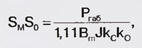
where U and I are the readings of the voltmeter PV1, V, and the ammeter PA1, A; F - frequency, Hz; S - cross-sectional area of the "experimental" magnetic core, cm2; w is the number of turns of its winding. From the graph obtained, as shown in the figure, the saturation induction Bs, the maximum induction Bm and the maximum strength of the alternating magnetic field Hm are found. For example, let's calculate a welding transformer designed to operate from an AC network of 220 V, 50 Hz, given the open-circuit voltage Uxx = 65 V and the maximum welding current Imax = 150 A. Overall power of the transformer Pgab=Uxx Imax = 65 150=9750 VA. According to the well-known formula, we determine the product of the cross-sectional area of the magnetic circuit SM and the area of its window So:
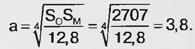
where J is the current density in the windings, A/mm2; ks=0,95 - filling factor of the magnetic circuit section with steel; Ko=0,33...0,4 - filling factor of its window with copper (aluminum). Suppose Bm=1.42 T, the primary winding is wound with copper wire, the secondary with aluminum (we take the average value of the current density J=6.5A/mm2): SMSo=9750/(1,11·1,42·6,5·0,37·0,95)= = 2707 см4. For rod transformers, the following size ratios are recommended [6] (see Fig. 8): b/a-2; c/a=1,6; h/a=2,5...5. Choosing h/a=4, we calculate the size a, cm:
Assuming a=40 mm, we find the remaining dimensions of the magnetic circuit: b=2a=80mm; c=1,6a=32 mm; h=4a=160mm. EMF of one turn of the transformer winding on such a magnetic circuit Ev \u2,22d 10-XNUMX-4Bmabkc=2,22 10-41,42 3200 0,95 = 0,958 V. Number of turns of the secondary winding w2=Uxx/Ev=65/0,958=68. Cross-section of the secondary winding wire S2=Imax/J=150/5=30 mm2 (J=5 A/mm2, since the secondary winding wire is aluminum). The number of turns of the primary winding w1=U1/EB=220/0,958=230. The maximum current of the primary winding I1max=lmax·w2/w1=150-68/230=44,35 A. The cross section of the copper wire of the primary winding S1=l1M/J=44,35/8=5,54 mm2. Both the primary and secondary windings of a rod-type transformer are usually divided into two identical parts, placing them on two cores of the magnetic circuit. Each of the series-connected parts of the primary winding is 115 turns of wire with a diameter of at least 2,65 mm. If the parts of the primary coil are supposed to be connected in parallel, each should contain 230 turns of wire of half the cross section - with a diameter of at least 1,88 mm. Similarly, they are divided into two parts and the secondary winding. If the windings are made cylindrical, in order to obtain a falling load characteristic of the transformer, a resistor with a resistance of 0,2 ... 0,4 Ohm should be connected in series with the secondary from a nichrome wire with a diameter of at least 3 mm. For a transformer with disc windings, this resistor is not required. Unfortunately, an accurate calculation of the leakage inductance of such a transformer is practically impossible, since it even depends on the location of nearby metal objects. In practice, the calculation is carried out by the method of successive approximations with the adjustment of winding and structural data of the transformer according to the results of testing the manufactured samples. A detailed technique can be found in [7]. In amateur conditions, it is difficult to manufacture a transformer with movable (to adjust the current) windings. To get several fixed current values, a secondary winding is made with taps. More precise adjustment (in the direction of decreasing current) is carried out by adding a kind of inductance coil to the circuit - laying the welding cable in a bay. Before proceeding with the manufacture of the calculated transformer, it is advisable to make sure that its windings will be placed in the magnetic circuit window, taking into account the necessary technological gaps, the thickness of the material from which the frame is made, and other factors. Dimensions c and h (see Fig. 8) must be "adjusted" in such a way that each layer of the winding fits an integer number of turns of the selected wire, and the number of layers is also an integer or slightly less than the nearest integer. Space for interlayer and interwinding insulation should be provided. The most successful variant is not always obtained on the first attempt, often it is necessary to repeatedly and quite significantly adjust the width and height of the magnetic circuit window. When designing cylindrical windings, it is necessary to optimally choose the sizes of their sections. Usually, a secondary winding wound with a thick wire is given more space than a primary. A sketch of the design of the transformer for two values of welding current - 120 and 150 A - is shown in fig. 11, and the circuit of its inclusion - in fig. 12.
A smaller current corresponds to a larger number of turns of the secondary winding. It's not a mistake. It is known that the winding voltage is proportional to the number of its turns, and the leakage inductance increases in proportion to the square of their number. As a result, the current decreases. The windings are placed on two frames made of sheet fiberglass with a thickness of 2 mm. The sections of the primary and secondary windings on each frame are separated by an insulating cheek of the same material. The holes in the frames for the magnetic circuit are 1,5 ... 2 mm wider and longer than the cross section of the latter. This eliminates assembly problems. In order to prevent deformation of the frame, during winding it is tightly planted on a wooden mandrel. The primary winding consists of two sections (I' and I "), located on different frames and connected in parallel. Each of the sections is 230 turns of PEV-2 wire with a diameter of 1,9 mm. If there is a wire with a diameter of 2,7 mm, in sections can be wound on 115 turns, but they will have to be connected in series.Each layer of wire before winding the next one should be compacted with light blows of a wooden hammer and smeared with impregnating varnish.Pressboard (electric cardboard) 0,5 ... 1 mm thick is suitable as interlayer insulation. For the secondary winding, the author used an aluminum bus with a cross section of 30 mm2 (5x6 mm). If you have a busbar with approximately the same cross-sectional area but a different size, you will have to slightly change the width of the carcass sections to accommodate the winding. Before winding, the bare busbar should be tightly wrapped with keeper tape or thin cotton fabric, previously cut into strips 20 mm wide. Insulation thickness - no more than 0,7 mm Sections II' and II" each have 34, sections III' and III" each have 8 turns. The bus is laid on the frame in two layers with the wide side towards the magnetic core. Each layer is compacted with light blows of a wooden hammer and liberally smeared with impregnating varnish. Manufactured coils should be dried. The temperature and duration of drying depend on the brand of impregnating varnish. The magnetic core of the transformer is assembled from plates of cold-rolled transformer steel with a thickness of 0,35 mm. Unlike almost black hot-rolled steel, the surface of cold-rolled steel is white. You can use sheet steel from the magnetic circuits of failed transformers installed at transformer substations. It is desirable to test steel according to the method described above. If the value of the maximum induction Bm obtained empirically differs significantly from that adopted in the calculation (1,42 T), the latter will have to be repeated and the results taken into account in the manufacture of the transformer. Steel sheets are cut in the direction of rolling into strips 40 mm wide, which are cut into plates 108 and 186 mm long. Burrs are removed with a file or file with a fine notch. The magnetic circuit is assembled "vpe-lid" with the smallest possible gaps at the joints of the plates. The finished transformer is placed in a protective casing made of a non-magnetic material, such as aluminum. Ventilation holes must be made in the casing. The transformer is connected to the 220 V network with a cable with copper power conductors with a cross section of at least 6 mm2 and a ground wire, which is connected to the magnetic circuit of the transformer and its protective casing. The mains socket must be a three-pin (the third one is grounded), rated for a current of at least 63 A. The conclusions of the secondary windings are securely connected to threaded brass studs with a diameter of 8 ... 10 mm, mounted on a heat-resistant dielectric panel mounted on the protective casing of the transformer. Soft copper wires with a cross section of 16 ... 25 mm2 are suitable as welding wires. Welding electrodes (in the absence of ready-made ones) can be made independently, using, for example, the recommendations from [8]. A wire with a diameter of 2 ... 6 mm from mild mild steel is divided into straight segments 300 ... 400 mm long. The coating is prepared from 500 g of chalk and 190 g of liquid glass, diluted with a glass of water. This amount is enough for 100-200 electrodes. The prepared pieces of wire are immersed in the coating for almost the entire length, leaving only the ends approximately 20 mm long uncovered, removed and dried at a temperature of 20 ... 30 ° C. Such electrodes are suitable for welding with both alternating and direct current. Of course, they can only serve as a temporary alternative to those produced in an industrial way. They should not be used for responsible work. Literature
Author: V.Volodin, Odessa, Ukraine
Air trap for insects
01.05.2024 The threat of space debris to the Earth's magnetic field
01.05.2024 Solidification of bulk substances
30.04.2024
▪ Electric generator runs on friction ▪ Data transfer speed will double ▪ RAK811 is a budget LoRa module for the Internet of Things ▪ Poplars will learn to decompose poisons
▪ section of the site Calls and audio simulators. Article selection ▪ article by Lawrence Stern. Famous aphorisms ▪ How many surnames are there in South Korea? Detailed answer ▪ Electrician article. Job description ▪ article Refinement of the phone. Encyclopedia of radio electronics and electrical engineering
Home page | Library | Articles | Website map | Site Reviews
www.diagram.com.ua |


 Leave your comment on this article: