|
|


 Arabic
 Bengali
 Chinese
 English
 French
 German
 Hebrew
 Hindi
Hindi Italian
 Japanese
 Korean
 Malay
Malay Polish
 Portuguese
 Spanish
 Turkish
 Ukrainian
 Vietnamese
|
ENCYCLOPEDIA OF RADIO ELECTRONICS AND ELECTRICAL ENGINEERING Automatic protection of radio equipment from overloads when turned on
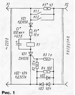
Encyclopedia of radio electronics and electrical engineering / Protection of equipment from emergency operation of the network, uninterruptible power supplies When various radio equipment is turned on, especially with powerful transformer power supplies, transient processes occur (in particular, characteristic of large starting currents) that can disable some radio elements. In addition, they lead to fluctuations in the mains voltage, which can cause malfunctions in other devices, such as electronic watches. To smooth these processes, devices for limiting the initial current are sometimes used [1]. By the way, similar devices were used in televisions produced about two decades ago. But they were not perfect, because they were installed inside the TV, and they had to be turned on only after the mains was turned on by the main switch. The task of protection can be simplified, for example, by using a device for dependent activation of various devices [2]. A slight refinement of such a device will make it possible to achieve automation of the protection of radio equipment when it is connected to the network. The scheme of the automaton is shown in fig. 1. It works like this. As soon as the device is turned on, the current it consumes flows through the limiting resistor R5, as well as through the diodes VD2-VD4 and the resistor R4. The current through the load will be limited by the resistance of the resistor R5. With a positive half-cycle of the mains voltage at the top pin of the X1 plug according to the circuit, it will be applied through the diode VD1, the resistor R1 and the capacitor C1 to the anode of the trinistor VS1. At the same time, the positive voltage falling on the diodes VD3, VD4 is supplied to the control electrode of the trinistor. It opens and the capacitor starts charging. With a negative half-cycle, the trinistor closes.
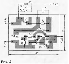
After several half-cycles, the voltage across the capacitor will reach a value at which relay K1 will operate. Its contacts K1.1 and K1.2 will supply the load with the full mains voltage. Since the charging current of the capacitor is much greater than the discharge current (through the relay winding), the relay remains in the same state as long as the load is switched on. As soon as the load is de-energized by a standard switch, the trinistor will stop opening, the capacitor will be discharged onto the relay winding, its contacts will open and the machine will go into standby mode. What parts can be used in the machine? Diode VD1 - any rectifier with a reverse voltage of at least 350 V, VD2-VD4 must be rated for the current consumption of the protected device. Resistor R5 - with a power of 10-15 W, it is permissible to use several MLT-2 resistors connected in series or in parallel. The remaining resistors are MLT, S2-33. Capacitor - series K52, K53. The relay is a high-resistance relay with a tripping current of not more than 15 mA, an operating voltage of 30 ... 50 V and contacts designed for switching loads of the corresponding power. Most of the parts are placed on a printed circuit board (Fig. 2) made of one-sided foil fiberglass. In the manufacture of a device in the form of a set-top box, the board, together with the relay and resistor R5, is placed in a case made of insulating material, on which the X2 power outlet is fixed. A power cord of the required length is removed from the housing with an X1 plug at the end. A variant is possible in which the plug pins are attached to the body, as in network adapters.
When setting up the machine, first select the resistor R1 until a stable operation of the relay is obtained at the minimum mains voltage. The capacitor must be of such a capacity that the desired delay in the operation of the relay is provided. By selecting the resistor R5, the necessary limitation of the load current is set depending on its power [1]. Literature
Author: I. Nechaev, Kursk
Machine for thinning flowers in gardens
02.05.2024 Advanced Infrared Microscope
02.05.2024 Air trap for insects
01.05.2024
▪ Biocompatible electrode cloth for clothing ▪ Nanomaterial of molecules twisted simultaneously in opposite directions
▪ section of the site History of technology, technology, objects around us. Article selection ▪ Lefty article. Popular expression ▪ article Is it true that a person yawns only when he is tired? Detailed answer ▪ article Subwoofer Thunder V-150. Encyclopedia of radio electronics and electrical engineering ▪ article The map is nailed to the wall. Focus Secret
Home page | Library | Articles | Website map | Site Reviews
www.diagram.com.ua |

 Leave your comment on this article: