|
|


 Arabic
 Bengali
 Chinese
 English
 French
 German
 Hebrew
 Hindi
Hindi Italian
 Japanese
 Korean
 Malay
Malay Polish
 Portuguese
 Spanish
 Turkish
 Ukrainian
 Vietnamese
|
ENCYCLOPEDIA OF RADIO ELECTRONICS AND ELECTRICAL ENGINEERING Subwoofer Thunder V-150. Encyclopedia of radio electronics and electrical engineering
Encyclopedia of radio electronics and electrical engineering / Speakers The design of the bass link I proposed was experimental. First of all, I would like to mention all the multiple reviews about the "quality" of most Russian speakers, with which I completely agree. And despite this, nevertheless, I decided on such a "feat" and spent a certain amount of time and material resources. As it turned out in the end - not in vain ...
Here is the head itself. This is the workhorse of Russian speakers of the "Corvette" type, from where it was unscrewed ... Due to the novelty of the speaker, I had to paint it. Yes, straight from a can of automotive acrylic paint. Attaching photo. To calculate the case, I used the well-known program JBL Speaker Shop. By the way, who does not have characteristics for this work of Soviet engineers, I also attach it: Fs - 25Hz
After not long conclusions and poking the computer keys, the following case parameters were drawn:
Following the parameters of the case, I calculated the phase inverter. And it was calculated according to the principle of "Matarazzo" (design developer Jean-Piero Matarazzo). Matarazzo, in fact, proposed a new formula for calculating the phase inverter, which takes into account the influence of the wall of the speaker cabinet on the calculation of the length of the phase inverter.
Here the frequency is in hertz, the volume is in liters, and the length and diameter of the tunnel are in millimeters, as we are used to. This scientist proposed a solution regarding the case of the phase inverter itself, namely, to reduce the length of the phase inverter tunnel.
This geometry makes it possible to shorten the tunnel compared to the original, constant section, at least one and a half times, or even more.
What the dimensions in tables 3 and 4 mean will become clear from fig. D and d are the diameter of the cylindrical section and the largest diameter of the conical section, respectively, L1 and L2 are the lengths of the sections. Lmax is the total length of the hourglass tunnel, just for comparison, how much shorter it was made, but in general, this is L1 + 2L2. Technologically, making an hourglass with a circular cross section is not always easy and convenient. Therefore, here it can also be made in the form of a profiled slot (see Fig.). To replace a tunnel with a diameter of 80 mm, Matarazzo recommends choosing a slot height of 50 mm, and to replace a 100 mm cylindrical tunnel - equal to 60 mm. Then the width of the section of a constant section Wmin and the maximum width at the entrance and exit of the tunnel Wmax will be the same as in the table (the lengths of the sections L1 and L2 - as in the case of a circular section, nothing changes here). If necessary, the slot tunnel height h can be changed by simultaneously adjusting both Wmin and Wmax so that the values of the cross-sectional area (h.Wmin, h.Wmax) remain unchanged.
Here's what happened to me. The parameters are as follows:
A phase inverter was made of 5mm plexiglass, then painted black.
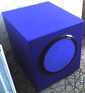
So the body. I will make a comment here on the bottom of the front and back walls - the front, as you can see, is double, glued and twisted. Holes for self-tapping screws were filled with auto putty. (In the photo they are not putty yet) And the self-tapping screws themselves are smeared with glue in order to exclude the possibility of twisting them from vibration (in my practice there have been cases). The ends of the wall are rounded. Chipboard material, like the whole body. All connections were glued with "liquid nails". The rear wall has a niche for placing an amplifier, a frequency cutoff control filter and a phase shifter there. the subwoofer was planned to be active. At the back, there is a hole for the phase inverter port.
After careful processing, the case was pasted over with a self-adhesive film for the future interior of my room. (The speaker system on the right, also of my manufacture, which I will also paste over in blue later).
The legs for the subwoofer were made of cone-shaped steel (but this, however, is no longer by me). The internal volume of the body is glued with sound insulation and a sound absorber is laid. (It is better not to save on these components). As for the amplifier, it was traditionally made on the famous integrated TDA7294. And no matter what they say about her, here, they say, shit, etc. for home-made subwoofer amplifier, I have not yet found a better one in terms of ease of tying / quality / cost.
Here is a diagram of the bridge connection of two microcircuits, with a total nominal output power of 150 watts. This is quite enough to build up 100GDN-3. Light blue capacitors are visible on the diagram - these are pass-through capacitors, you can put electrolytes instead of them (but I recommend putting non-polar ones). The board was etched with ferric chloride, the drawing was translated from a laser printer printout. The power supply is 2-pole, shunt capacitors and arresters are soldered in parallel to the power capacities. Diode motors with Schottky barrier, 10A, 1000V each. The earth is connected at one physical point. The wires connecting the power supply to the amplifier are selected with a section that provides current transmission up to 20A.
Schematic diagram of the amplifier
Schematic diagram of the power supply
Frequency cutoff regulator and phase shifter block
An adder and a first-order passive filter with a cutoff frequency of about 150 Hz are installed at the input. A 1nd order Butterworth filter is assembled on the transistor VT2. The cutoff frequency varies from about 50 to 200 Hz. A phase regulator is assembled on the op-amp. The lower limit of the range is 15 Hz. The input signal must not exceed 1 volt, otherwise distortion may occur. The input signal is weakened by 4-5 times (12-14dB), but, however, I had to bypass the resistors R1 and R2, because. the signal from the sound card of the computer is too weak (at least in mine). Before operation, it is necessary to select a resistor R6 until a voltage of 6+/-1V is obtained at pin 6 of DA0,5. All circuits are located on the back of the subwoofer:
In conclusion... of course, I did not expect to get anything worthwhile from this head, because. previously dealt with domestic heads. Maybe he began to use other calculations, or other principles of subwoofer construction, but from this, we can say a hopeless speaker, a decent sub turned out. True, its dimensions and weight ... but this has to be sacrificed for a good subwoofer from a Russian speaker. Yes, as for the bass, it's a good return already from 19 Hz! (according to the program and my ears). Tight, dynamic bass in music (drum and bass without pretensions), real special effects in movies (Jurassic Park in your house!) neighbors out! Author: Oleg Nikulin (liveofsou@mail.ru); Publication: cxem.net
Artificial leather for touch emulation
15.04.2024 Petgugu Global cat litter
15.04.2024 The attractiveness of caring men
14.04.2024
▪ ASUS VX279H-J and VX239H-J monitors ▪ Drinking water from lunar soil ▪ The electric scooter will follow the rules of the road
▪ section of the site Radioelectronics and electrical engineering. Article selection ▪ article Chewing gum for the eyes. Popular expression ▪ What were the main features of the Roman Empire? Detailed answer ▪ article locomotive driver. Job description
Home page | Library | Articles | Website map | Site Reviews
www.diagram.com.ua | |||||||||||||||||||||||||||||||||||||||||||||||||||||||||||||||||||||||||||||||||||||||||||||||||||||||||||||||||||||||||||||||||||||||||||||||||||||||||||||||||||||||||||||||||||||


 Leave your comment on this article: