|
|


 Arabic
 Bengali
 Chinese
 English
 French
 German
 Hebrew
 Hindi
Hindi Italian
 Japanese
 Korean
 Malay
Malay Polish
 Portuguese
 Spanish
 Turkish
 Ukrainian
 Vietnamese
|
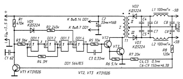
ENCYCLOPEDIA OF RADIO ELECTRONICS AND ELECTRICAL ENGINEERING Bipolar stabilized power supply, 3-15/±5 volts 0,25 watts. Encyclopedia of radio electronics and electrical engineering
Encyclopedia of radio electronics and electrical engineering / Power Supplies Many people are engaged in the development or improvement of bipolar stabilized power supplies for low-power radio equipment of measuring equipment. The proposed device may well replace, for example, the power supply of a digital multimeter, sometimes critical to start. The described stabilizer is simple, contains a relatively small number of elements and, as observations have shown, has good technical characteristics. It maintains performance without degradation from 3V to 15V input voltage, making it applicable to many other applications requiring a stabilized bipolar power supply.
The master oscillator of the stabilizer is made using a time-setting capacitor C1 and a Schmitt trigger made on the elements of the 564LE5 (DD1) microcircuit. When a high-level voltage is present at the output of the DD1.3 element, the VD1 diode is in the closed state, and the capacitor C1 is charged from the input voltage source through the resistor R1. As soon as the voltage on the capacitor reaches the trigger threshold, the trigger state will abruptly change to the opposite and a low voltage is set at the output of element DD1.3. Now the diode VD1 opens and the capacitor. C 1 is discharged through this diode, resistor R2 and the output of element DD1.3. When the voltage on the capacitor decreases to the trigger off threshold, it switches to its original state and the generator operation process is repeated. The output voltage is stabilized by the circuit VT1, R7, R8 as follows. While the voltage at the "+5 V" output is low, the transistor VT1 is closed and does not affect the operation of the generator - its output has the maximum possible pulse duration, and the pauses between them are minimal. At the output voltage of the specified value, the transistor VT1 opens, the charging time of the capacitor C1 increases, and the time it is discharged, on the contrary, decreases. Accordingly, the duration of the pulses that open the composite transistor VT2VT3 decreases, the pause between them increases, as a result of which the output voltage stabilizes. The stabilizer can use microcircuits of the 564, K561, KR1561 series, containing four inverters. Diodes - any high-frequency. Capacitors C2 and C6-C9 - oxide K52-1, K50-6, K50-16, the rest - K10-17, KM-5, KM-6. KT3102B transistors are interchangeable with a 1NT251 transistor assembly. Inductors L1 and L2 - DM-0,1 with an inductance of 100 μH. Transformer T1 is made on a magnetic circuit of size K16x10x4,5 made of M2000NM1 ferrite. Each of the transformer windings contains 100 turns of PELSHO 0,1 wire, but the primary winding is wound in two wires. Set up the device in this order. A load resistor with a resistance of 5 ... 5 Ohm is connected to the output of both arms of the stabilizer (between the +500 V and -600 V terminals). Then a supply voltage of 5 V is applied to the input of the device and the output voltage is measured with a voltmeter. The equality of the input and output voltages is achieved by selecting the resistor R8. After that, the input voltage is reduced to 3 V and the voltage at the output of the stabilizer is also controlled. In the event of a breakdown in the generation of the clock generator, a resistor R2 is selected. On this, the adjustment of the device can be considered complete. Author: A.Safronov
Machine for thinning flowers in gardens
02.05.2024 Advanced Infrared Microscope
02.05.2024 Air trap for insects
01.05.2024
▪ Fully functional 70 Mbit static memory chip ▪ Coca-Cola, Apple and IBM are the world's best brands ▪ Neuromorphic chips for artificial intelligence ▪ Jurassic crickets singing bass ▪ Interactive whiteboards in Moscow schools
▪ site section Parameters of radio components. Article selection ▪ article by Ramon Gomez de la Serna. Famous aphorisms ▪ article What do St. Bernards wear around their necks? Detailed answer ▪ Film checker article. Job description
Home page | Library | Articles | Website map | Site Reviews
www.diagram.com.ua |


 Leave your comment on this article: