|
|
ENCYCLOPEDIA OF RADIO ELECTRONICS AND ELECTRICAL ENGINEERING Antenna amplifier power supply option. Encyclopedia of radio electronics and electrical engineering
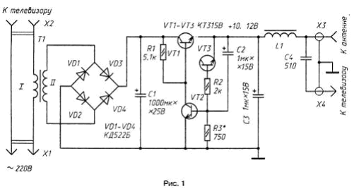
Encyclopedia of radio electronics and electrical engineering / Power Supplies Unlike other similar designs, the antenna amplifier power supply offered to the attention of readers does not contain its own switch and starts working simultaneously with turning on the TV. This device (Fig. 1), which is a stabilized voltage source of 10 ... 12 V at a load current of up to 20 mA, is suitable for powering relatively simple television antenna amplifiers and UHF converters. A distinctive feature of the unit is that instead of a classic transformer that lowers the mains voltage, it uses a current transformer T1, the primary winding of which is connected in series with the primary power circuit of the TV.
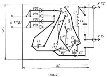
The current transformer, on the basis of which, for example, power consumption indicators are built, works as follows. The current flowing through the primary winding, consumed by the TV, creates a voltage drop of 2 ... 3 V on it. It does not exceed 1 ... 2% of the mains voltage and, of course, does not affect the normal operation of the TV. The alternating voltage of the secondary winding of the transformer is rectified by the bridge VD1 - VD4, and the ripple of the rectified current is smoothed out by the capacitor C1. A compensation voltage regulator is assembled on transistors VT1-VT3. From its output, a stabilized voltage of + 10 ... 12 V is fed through the inductor L1 to socket X3, to which the central wire of the antenna drop cable with an amplifier placed on it is connected. The X4 plug is connected to the antenna input of the TV. The mains plug of the TV is connected to the X2 jacks of the device, and the X1 plug is connected to the network. The device can use transistors KT315V - KT315E, KT312B or from the KT3102 series with letter indices A, B; diodes - any rectifier (preferably germanium). Capacitor C1 - K50-16, C2 and C3 - K50-6, C4 - KD, KG, KLS. Choke L1 type. DM-0,1 with an inductance of 20 ... 50 μH or home-made, made on a ring magnetic circuit with a diameter of 5 ... 10 mm from ferrite 1000 ... 2000 NN; the winding contains 30 turns of wire PEV-2 0,1 ... 0,15. The current transformer is wound on the magnetic circuit of the subscriber loudspeaker; the magnetic circuit of the transformers of the ultrasonic frequency converter of the Alpinist-407 radio receiver or similar is also suitable. The secondary winding is wound first, which contains 1000 turns of PEV-2 0,1 wire. Then, wrapping it with a layer of reliable insulation, the primary winding is wound, the number of turns of which depends on the power consumed by the TV. So, for a TV that consumes power of 60 W, the primary winding should contain approximately 150 turns of PEV-2 0,4 wire. For TVs with higher power consumption, the number of turns of this winding is reduced, and the diameter of the wire used for it is proportionally increased. The final number of turns of the primary winding of the transformer is established empirically when setting up the device. All parts of the power supply, except for detachable connectors and a transformer, are mounted on a printed circuit board made of foil fiberglass (Fig. 2). The board and the transformer are placed in a housing of suitable dimensions made of insulating material. Socket X2 and socket X3 are installed on the front wall of the housing. The conductor connecting the board to socket X3 must be of minimum length - no more than 20...30 mm. The finished power supply is placed on the back wall of the TV near the antenna jack, hooked to the air vent with a wire hook, or directly on the TV stand.
Testing and adjustment of the power supply is carried out in the following sequence. A load equivalent (resistor) with a resistance of 680 Ohms is connected to its output, and a voltage of 1 ... 15 V is applied to capacitor C20 from an external source. Then, by selecting resistor R3, a voltage of 3 ... 10 V is set at the output of the stabilizer (on capacitor C12). Next, the conductors of the secondary winding of the transformer are soldered to the board, and the power supply with the TV power cord connected to it is connected to the mains. After turning on the TV, the voltage across the capacitor C1 should be in the range of 15 ... 18 V. This can be achieved by appropriate selection of the number of turns of the primary winding of the transformer. The described version of the antenna amplifier power supply can become universal, i.e. suitable for TVs with different power consumption, if the primary winding of the current transformer is made with taps and switched depending on the TV model. In the case of joint operation of such a power supply with an antenna amplifier, the need for the inductor L2 and capacitor C9 of its decoupling power supply is eliminated. If interference appears in the form of horizontal stripes slowly moving across the screen, the rectifier bridge diodes must be shunted with ceramic capacitors with a capacity of several thousand picofarads. Author: I.Nechaev
Machine for thinning flowers in gardens
02.05.2024 Advanced Infrared Microscope
02.05.2024 Air trap for insects
01.05.2024
▪ Bilingualism improves brain development in children ▪ HDR10+ High Dynamic Range Open Video Standard ▪ PET plastic from biomass waste
▪ site section Clocks, timers, relays, load switches. Article selection ▪ article Of two evils always choose the lesser. Popular expression ▪ Why were people afraid of eclipses in the past? Detailed answer ▪ article Antillean cucumber. Legends, cultivation, methods of application ▪ article Musical garlands. Encyclopedia of radio electronics and electrical engineering ▪ article Once again about the Ural 84M. Encyclopedia of radio electronics and electrical engineering
Home page | Library | Articles | Website map | Site Reviews www.diagram.com.ua |


 Arabic
 Bengali
 Chinese
 English
 French
 German
 Hebrew
 Hindi
Hindi Italian
 Japanese
 Korean
 Malay
Malay Polish
 Portuguese
 Spanish
 Turkish
 Ukrainian
 Vietnamese


 Leave your comment on this article: