
|
|
ENCYCLOPEDIA OF RADIO ELECTRONICS AND ELECTRICAL ENGINEERING Once again about the Ural 84M. Encyclopedia of radio electronics and electrical engineering
Encyclopedia of radio electronics and electrical engineering / Civil radio communications After repeated repetition of the Ural 84M transceiver, some of its components had to be slightly modified. The quality of the transceiver's work has improved, its reliability has improved, and tuning has become easier. 1. Power Supply The power supply proposed by the author "Ural 84m" was not repeated, because. I do not see the point of using RF and microwave transistors in this node. I use two separate sources to get +12 V and +40 V. The +12 V stabilizer is easiest to perform on the KREN8B MS. The +40 V stabilizer is made according to the circuit shown in fig. 1. It is not afraid of short circuits in the load and is very convenient in that the regulating transistor is directly attached to the chassis without insulating gaskets.
Some radio amateurs complain about the background of alternating current, which arises from the pickup of a power transformer on TOT13. This defect can be easily avoided by using a TOR core in a power transformer. PL-type cores have slightly worse parameters, and cores assembled from W-shaped plates give the worst results. In practice, transformers of any type can be used, but we must not forget that in connection with our "economical economy", usually during industrial winding, wire is saved and the network winding is not winded. Because of this, the no-load current increases and the leakage field of the transformer increases. The tip on TOT13 is also growing. The quality of the network winding is easy to check by measuring the no-load current. Acceptable is the current of a transformer with an overall power of 60 ... 90 W within 10 mA. If it is larger, the network winding is wound. Sometimes it is possible to reduce the background a little with the help of shielding with tin. 2. Output stage I often hear complaints and complaints on the air about the unreliability of the output stage at KP904. In most cases, this is due to careless and illiterate handling of this transistor. We must not forget that this is not a lamp and by the "redness of the anode" (as some NAM do) it will not be possible to pick up the P-circuit. Most often, the transistor is penetrated by static, which is induced in the antenna during a thunderstorm, or in winter when it snows. To get rid of this trouble, you need to make an antenna switch in which non-working antennas are grounded and the transceiver input is grounded through a choke with an inductance of at least 500 μH. It is also useful to ground the antenna socket in the transceiver itself through a similar choke. The gate transistor fails due to driver excitation. There is no need to try to “pump out” the maximum voltage from the driver. Here it is better to limit the voltage at the driver output to 7...10 V rms, but to achieve stable operation and an increase in the frequency response in the HF ranges. For this, C15, R14 are selected in node A2. The work will be more stable if KT4A is used as VT922. Instead of L3,4 “binoculars”, I use a transformer with a volumetric turn. Rings-1000 NN (NM) K10x6x3; L3 - 12 turns with a diameter of 0,3...05 mm; L4 - 6 turns with a diameter of 0,5...0,6 mm. Instead of T1, you can install a transformer on the ring 1000HH (HM) K10x6x3 L2-7 turns into two wires with a diameter of 0,3 ... 0,35 mm; L1 -5 turns with a diameter of 0,5 ... 0,6 mm. If, nevertheless, the driver is prone to excitation, it is possible to limit the RF voltage in the KP904 gate by installing a chain of series-connected high-frequency diodes (KD503; KD514, etc.) and a 10V zener diode on the case. The output stage on KP904A reliably operates at a voltage of 38 V with an output power of 25 ... 30 W. In this mode, it can withstand almost any SWR and load breaks. No need to be upset if it is not possible to find a 300 HH ring in the output stage. You can use a ring of a different permeability with a diameter of at least 20 mm, you only need to select the number of turns to equalize the frequency response. For example, on a 1000 NN (NM) ring, it is enough to twist (one turn per 5 ... 7 mm) from six PEV wires 0,35 mm to wind 5 turns. L7 and L8 must be obtained by dividing the twist into two windings of three wires. It is possible to use "binoculars" from rings 2000 ... 1000NN (NM) K10x6x4 as this transformer, in each column - 5 ... 3 knees. The winding in the load circuit has 4 ... 3 turns, the tube - in the drain circuit. And once again I repeat that one should not expect the same reliability from a transistor output stage as that of a tube one. 107. GPA When repeating the transceiver in this node, a variety of options were used - from the VPA with frequency division based on the PXNUMXM block to the option from the Rosa transceiver. No noticeable difference in the quality of the transceiver was noticed. Frequency multiplication in the GPA was not applied. Here you should pay attention to the fact that in order to get an ideal sinusoid at the output of the GPA, you need to remove the signal not from any electrode of the master oscillator transistor, but directly through the capacitance from the generator circuit. In this case, a field effect transistor must be used as a buffer stage. In order to reduce the initial frequency overrun when switching from range to range, it is necessary to use the minimum possible current through the master oscillator transistor. An effective measure to reduce the initial frequency overrun turned out to be the use of a radiator for the master oscillator transistors. For these purposes, the side wall of the GPA block made of aluminum 5 mm thick was used, recesses were drilled in it, where the caps of the transistors of the master oscillators were pressed tightly, from which the paint was previously peeled off. The caps of the transistors for better heat transfer can be lubricated with thermally conductive grease. In this version of the GPA, the frequency overshoot is observed only in the first 2 ... 3 minutes.
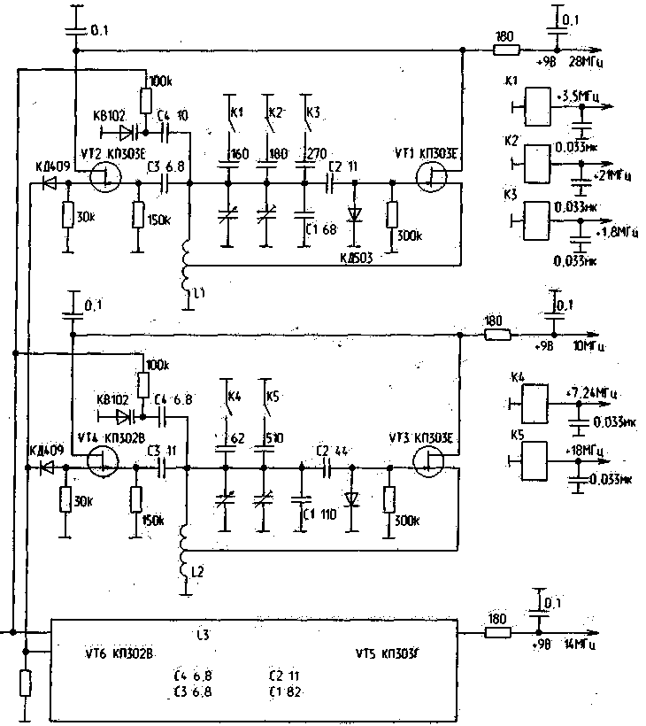
I give the data of one of the GPA options (Fig. 2), in my opinion, with good parameters. It uses a three-section KPE from the R105D radio station with the same coils that are installed inside the KPE. It is possible to use a three-section KPI from broadcast receivers, you only need to thin out the sections so that the maximum capacitance is no more than 50 pF. To obtain the required frequencies of nine ranges, additional capacitors are connected using a relay. The use of relay contacts in frequency-setting circuits practically did not worsen stability. One section of the KPI is used to build a 20 m range generator. The second section combines the "narrow" ranges -10, 7,24,18 MHz, the third section is used for the "wide" range generator - 28; 3,5; 21:1,8 MHz. This division is, of course, conditional, but in this scenario, the "extra" overlap in frequency is reduced. I propose the option of introducing additional bands into an already working transceiver. To obtain the required frequencies, relays (RES49; RES55) are installed in the GPA, which connect additional capacitors of the new ranges. It should be noted here that in order to minimize the influence of the relay contacts on the stability of the generators, the “cold” leads of the capacitors should be switched. Additional bandpass filters and output P-filters can be omitted. All ranges can be provided using the same A2 board and P-filters of the output stage for 6 ranges.
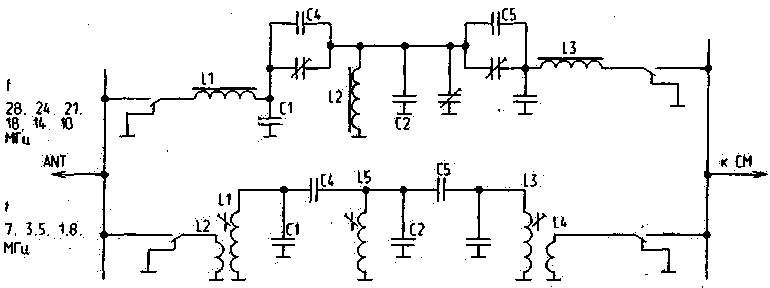
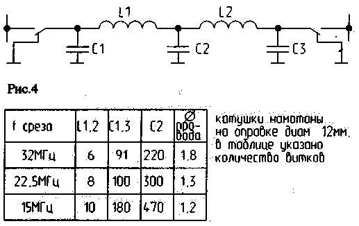
The bandwidths of the band pass filters are expanded to obtain additional ranges (Figure 3-4). Now the 28 MHz "bandpass" passes the frequencies of the 24 MHz band, the next - the frequencies of the 21 and 18 MHz bands, the third - the frequencies of the 14 and 10 MHz bands. The filter data is taken from Red's book "High Frequency Circuitry...". But since our industry does not produce rings similar in parameters to those given in the book, we had to look for a suitable replacement. After numerous experiments, an acceptable option was obtained using halves of the SB9A and SB12A cores. Half of the core is used as a ring, without any alterations. In the absence of a capacitance meter, it is desirable to install trimmer capacitances, as shown in the DFT diagram. In table. 1, 2 give the number of turns and capacitance in pF without "trimmers". Table 1
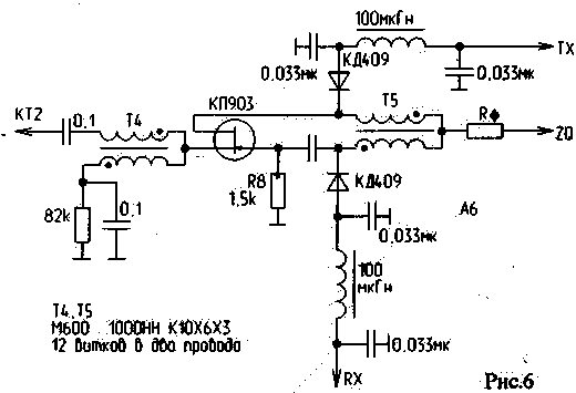
The filters are of good quality. In terms of attenuation in the transparency band, they are similar to double-circuit filters on cores with a diameter of 12 mm. The original strips have 3 dB more attenuation in the transparency band. Table 2 shows the updated data for low-pass bandpass filters. P-filters of the "upper" ranges are also being redesigned. In the author's version, they have a Chebyshev characteristic, so they "fill up" new ranges. The filters are converted to two-section ones with a Butterworth characteristic. Compared to copyright, they provide more attenuation beyond the passband. 4. Board A6 Repeated attempts to improve the parameters of the transceiver by simply replacing the diodes in the mixer with some kind of "superdiodes" did not give positive results. A variety of diodes were tested in the mixer - KD512, KD514, AA112, AD516, KD522, KD503, KD922, D18, D9, etc. A deterioration in sensitivity and dynamic range was observed only when switching from silicon diodes to germanium diodes. The sensitivity for different diodes ranged from 0,4...0,5 µV. Second order intermodulation interference D3=-86...91dB. The measurements were carried out with the device and methodology proposed by UY5DJ in the range of 20 m. The best parameters are obtained by using selected diodes (KD922) and carefully, symmetrically made transformers. Attempts to balance the mixer by introducing tuning capacitors connected to any arm of the bridge do not improve the quality of the mixer. Balancing is achieved, but only at a specific frequency. When switching to another range, these capacitors further unbalance the mixer and worsen its parameters. Good parameters are obtained when using conventional KD503, selected at least by a tester based on forward and reverse resistance. Figure 6 shows the inclusion of a “diplexer” on KP903 with an additional matching transformer T4. In this connection option, the transmission coefficient of this cascade increases for both reception and transmission.
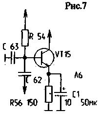
For high-quality operation of the cascode amplifier on KP312...KP303, these transistors must be selected according to their slope. They should be approximately equal in this parameter. Many radio amateurs are trying to replace the K224UR4 with a supposedly less noisy one of a different type. In my opinion, there is no point in doing this, because... the maximum sensitivity should be determined by the first stage of the receiver, i.e. in our case, it is the first mixer, and the sensitivity of the amplifier is its first stage. There is no need to achieve the maximum possible gain from this MS; here the sensitivity of the transceiver needs to be “searched” for in the first stages. Experiments using ICs of different years of production 2US248 and 224UR4 (they are absolutely identical) showed their equivalence in terms of Ksh and Ku. It is advisable to reduce the MS bandwidth. To do this, a capacitor with a capacity of 3...68 pF is installed on the case from the 100rd pin of the MS. There is no need to increase the supply voltage of this MS above 9V. Significantly increase Kus. low frequency amplifier is possible by turning on C1 as shown in Fig.7. For high-quality operation of the AGC, you need to use the KP303E of the AGC amplifier with a minimum steepness. In order to select a transistor with the required transconductance, I use the simplest comparative measurement. Through
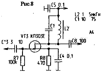
Using a milliammeter (tester), I apply a positive voltage of 10... 12 V to the drain of the transistor being measured, and a minus voltage to the gate and source connected together. The dependence is directly proportional - transistors with a large current have a greater slope and vice versa. 5. Board A4 Here it is necessary to increase the values of the resistors R12 and R6 to 47 ... 56K. This reduces the current through the varicaps and we get rid of the constant unbalance of the modulator. You can raise the amplitude of the reference oscillator to the modulator by making the cascade on VT3 resonant. To do this, L2 uses a 1 ... 5 μH inductor, which is tuned to resonance by capacitor C1 as shown in Fig. 8.
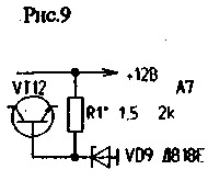
6. Board A7 Sometimes the +9V stabilizer does not start. For more stable operation, you need to install a resistor R1, as shown in Fig. 9.
It should also be noted that the high-quality operation of the A6 and A4 boards is possible when the foil used as a common wire is left on the part installation side. Comparison of the reception of such "devices" as RA3AO, Ural 84M, UA1FA ("I'm building a KB station"), the receiver "Katran", UW3DI showed that on the low bands at maximum interference levels "Ural 84M" is inferior only to the RA3AO transceiver. Fans of "pulling" weak telegraph signals on the HF bands, especially if random "ropes" are used as an antenna, the Katran receiver is more suitable. But this advantage is noticeable only if the range is "quiet". During the competition it is better to use RA3AO and Ural 84M transceivers. Author: A. Tarasov (UT2FW), Odessa region, Reni; Publication: N. Bolshakov, rf.atnn.ru
Machine for thinning flowers in gardens
02.05.2024 Advanced Infrared Microscope
02.05.2024 Air trap for insects
01.05.2024
▪ MOTOROLA FV500AA Compact Radio ▪ Epson Perfection Professional Flatbed Scanners ▪ Men spread negative information less often than women
▪ section of the site Life of remarkable physicists. Article selection ▪ article And the ball is over. Popular expression ▪ article Head of the economic department. Job description ▪ article Winding wires. Encyclopedia of radio electronics and electrical engineering
Home page | Library | Articles | Website map | Site Reviews www.diagram.com.ua |


 Arabic
 Bengali
 Chinese
 English
 French
 German
 Hebrew
 Hindi
Hindi Italian
 Japanese
 Korean
 Malay
Malay Polish
 Portuguese
 Spanish
 Turkish
 Ukrainian
 Vietnamese

 Leave your comment on this article: