|
|


 Arabic
 Bengali
 Chinese
 English
 French
 German
 Hebrew
 Hindi
Hindi Italian
 Japanese
 Korean
 Malay
Malay Polish
 Portuguese
 Spanish
 Turkish
 Ukrainian
 Vietnamese
|
ENCYCLOPEDIA OF RADIO ELECTRONICS AND ELECTRICAL ENGINEERING Musical garlands. Encyclopedia of radio electronics and electrical engineering
Encyclopedia of radio electronics and electrical engineering / Beginner radio amateur A simple way to make a similar garland is to use a musical synthesizer of the UMS series. A diagram of a device that allows you to control four groups of garlands of five LEDs each is shown in fig. 1. The basis of the machine is a node for continuous playback of melodies on a Schmitt trigger, made on transistors VT1, VT2, and an UMS chip (DD1).
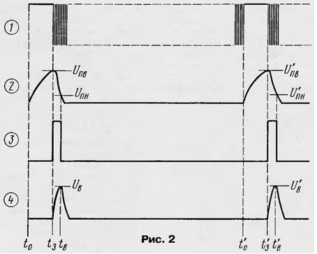
The DD2 counter together with the DD3 chip and the keys on the transistors VT4 - VT7 controls the switching of the garlands on the LEDs HL1 - HL20. Chip DD1, in addition to the function of a musical synthesizer, also serves as a master oscillator for the operation of garlands. The speed of switching garlands depends on the frequency of the 3H signal coming from this microcircuit to subsequent stages. Diodes VD2-VD4 together with resistor R10 form a parametric stabilizer for a voltage of about 2 V to power the DD1 chip. Let's start our acquaintance with the operation of the automaton from the node of continuous playback of melodies, simultaneously studying the diagrams (Fig. 2) at its various points. When the supply voltage is turned on, the DD2 counter will be in an arbitrary state, so the LEDs of different groups can also light up randomly. At the output 14 of the DD1 chip, a high logic level will be set (the moment in diagram 1) in relation to the plus of its power supply. Capacitor C1 will begin to charge through resistors R1 and R8 (diagram 2) during the time from t0 to t3 (about 2 s).
When the voltage on it reaches the switching threshold of the Schmitt trigger Unv (t3), the trigger will switch to another stable state, the voltage on the collector of the transistor VT2 will increase abruptly to 2 V (diagram 3). This level will go to pin 13 of the DD1 chip and turn on the playback of the melody. At pin 14 of the microcircuit, 3H pulses will appear, which, through the diode VD1 and the resistor, will discharge the capacitor C1 to the lower threshold voltage of the Schmitt trigger - Unn. But during the time while the trigger output is high, the capacitor C7 will start charging through the resistor R2 (diagram 4). As soon as the voltage on this capacitor reaches the threshold for switching on the melody selection (pin 6 DD1) Uv at time tv, the DD1 chip will switch to playing the next melody. The time interval between τ and tv is relatively short (0,1 ... 0,3 s), therefore the first, initial, melody is practically not played, and playback begins, in fact, with the next one. While the melody sounds, the capacitor C1 is almost discharged. This period occupies the time interval between tw and t0. At the moment t0 (diagram 1), the playback of the melody ends, a high level reappears at pin 14 of the DD1 chip. Capacitor C1 starts charging again to voltage Unv. Then the DD1 chip will turn on again to play the melody. As a result, the BF1 piezo emitter will sequentially play all the melodies recorded in the ROM of the microcircuit. The sound volume is regulated by a variable resistor R9. The 3H signal from pin 1 of the DD1 chip is fed through the level converter on the transistor VT3 to the counting input of the binary counter DD2 (pin 10). The counter counts pulses, and a binary code is formed at its outputs. You can, of course, connect the garland control keys to the outputs, but to get a greater variety of options for turning on the garlands, a kind of decoder on logical elements 2OR-NOT (DD3 chip) is used. Each element is connected with its inputs to two different counter outputs. Moreover, it is permissible to choose connection options independently. It should only be borne in mind that the younger the counter output, the higher the frequency of flashing the garland, and vice versa. A transistor switch is connected to the output of each logic element. For example, a key on a VT4 transistor is connected to the upper element according to the scheme, which controls the ignition of a garland of five LEDs - HL1-HL5. The remaining keys (on transistors VT5 - VT7) control other groups of LEDs. Moreover, the keys open, which means that the LEDs are lit, with a low level at the outputs of the elements. With a given supply voltage, the number of LEDs in each garland can be increased to six. But a variant is possible in which it is permissible to install 15 LEDs in each garland (Fig. 3). The currents in the garland circuits are equalized by selecting the appropriate limiting resistors.
In addition to that indicated on the diagram, the UMS8-08 music synthesizer is suitable. The remaining microcircuits are of the indicated types of the K176, K564, KR1561 series or imported analogues. Transistors VT1 - VT3 - any of the KT315, KT3102, VT4-VT7 series - any of the KT361, KT3107 series. Diodes - any of the KD503, KD521, KD522 series. Piezo emitter - any other, except for that indicated on the diagram, for example, ZP-1, ZP-2, ZP-22. LEDs - any domestic or imported different colors of glow. To power the machine, a block or adapter with a stabilized output voltage of 12 ... 15 V at a load current of 100 ... 300 mA is suitable. Establishing the device consists in selecting a resistor R1 of such resistance that the pause between melodies is about 2 s. If the pause is shorter, it is possible to turn on the microcircuit again without selecting a melody. Perhaps, for a clearer operation of the melody selection node, you will have to select a resistor R7. In the proposed version of the automaton, the groups of garlands are switched pseudo-chaotically at a rate that depends on the frequency of the 3H signal. By slightly modernizing the device, you can get the effect of a "running shadow" with a changeable, also depending on the frequency of the 3H signal, the switching speed. To do this, instead of the K561LE5 chip, install the K561IE8 (Fig. 4) and connect its input (pin 14) to any output of the DD2 counter.
The lower the bit, the higher the switching frequency. Author: I.Potachin, Fokino, Bryansk region
Traffic noise delays the growth of chicks
06.05.2024 Wireless speaker Samsung Music Frame HW-LS60D
06.05.2024 A New Way to Control and Manipulate Optical Signals
05.05.2024
▪ Tamron 16-300mm F/3.5-6.3 Di II VC PZD Macro Lens (Model B016) ▪ Ultra-clean diamond wafers with up to 25 EB of data
▪ section of the website Audiotechnics. Article selection ▪ article Nails would be made of these people. Popular expression ▪ Barosma article. Legends, cultivation, methods of application ▪ article Latvian proverbs and sayings. Large selection
Home page | Library | Articles | Website map | Site Reviews
www.diagram.com.ua |


 Leave your comment on this article: