|
|
ENCYCLOPEDIA OF RADIO ELECTRONICS AND ELECTRICAL ENGINEERING Inverter current source. Encyclopedia of radio electronics and electrical engineering
Encyclopedia of radio electronics and electrical engineering / Voltage converters, rectifiers, inverters The proposed inverter current source can be used to power electronic devices and charge car batteries. Flyback current converters (OHP) - inverters - consist of a powerful pulse switch. Unlike a push-pull converter, they have fewer radio components, the stabilization of the operating mode is carried out by feedback through optoelectronic switches from the output stages to the control input of the pulse-width control signal generator. The disadvantage of such converters is the need to use power transistors with a high operating voltage. the inverter current source has several degrees of protection against damage:
The flyback converter circuit with a current pulse switch (Fig. 1) consists of a PWM generator on an analog timer chip, a key transistor, output voltage stabilization circuits, current and thermal protection electronic circuits.
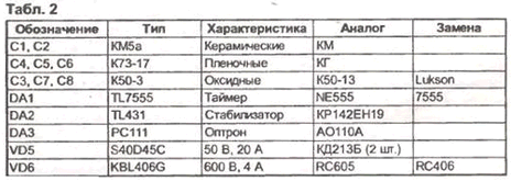
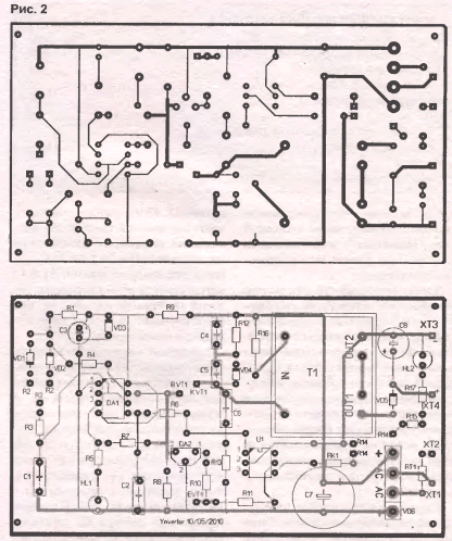
Power supply - transformerless with inrush current limitation. The primary and secondary circuits of the electronic circuit are galvanically separated. The high-frequency transformer of the converter is made on a ferrite core. Converter power depends on the supply voltage; conversion frequency and magnetic properties of the transformer. the use of a field-effect transistor as a key makes it possible to reduce signal losses in control circuits. The output current is controlled by changing the duration of the generator pulses at a constant frequency. The inverter has a triple voltage conversion. The alternating voltage of the mains is rectified by a powerful diode bridge and converted into a high-voltage DC. Then it is converted by the inverter into a high-frequency pulse, which is lowered by a pulse transformer. After it is rectified and smoothed, a low-voltage DC voltage of the required value is applied to the load. The pulse generator is made on an analog timer DA1. The microcircuit includes two comparators, an internal trigger, an output amplifier to increase the load capacity, and a key open-collector discharge transistor. The generation frequency is set by an external RC chain. The comparators switch the internal trigger when the threshold voltage on the capacitor C1 1/3 and 2/3 U pit is reached. The control input (pin 5) DA1 is used to change the pulse generation mode, which ensures the stabilization of the output voltage. The output current of the device depends on the duty cycle of the generator pulses, which is set by the tuning resistor R2. the pulse supplied to the key transistor VT1 from the output DA1 is very short, and the average current in the load is minimal. In the right position of the R1 slider, the pulse duration is maximum, as is the output current. The voltage inverter consists of a powerful field-effect transistor VT1 and a high-frequency transformer T1. To protect the transistor from breakdown by impulse voltages that occur during conversion, the transistor and transformer are "tied" with damping chains C4-C5-R12-VD4 and C6-R13 [2]. The protection of the transistor VT1 against overcurrent is made on a parallel stabilizer ("controlled zener diode") DA2. An increase in voltage across the resistor R11 in the source circuit of VT1 with an increase in current through it leads to the opening of DA2 and shunting of the VT1 gate. As a result, VT1 closes, and the current through it drops. The secondary circuits of the source include a rectifier on a high-frequency diode assembly VD5 and a smoothing filter C8-L1. The load current is controlled by a PA1 ammeter with an internal 10 A shunt. The power circuits of the inverter are made on a pulsed diode bridge VD6 and a filter capacitor C7. The charge of the filter capacitor at the initial moment is limited by the thermistor Rt2, which protects the diode bridge from damage by critical currents. the pulsed current through the transformer and the field-effect transistor is limited by the resistor R16, the resistance of which compensates for the spread in the parameters of the transformers. Inverter conversion frequency plays a big role in getting the maximum power from the device. With its increase by 10 times, the permissible power of the transformer (without changing the ferrite and windings) increases by almost 4 times. Ferrites are usually used in home-made inverter sources, providing inverter operating frequencies from 25 to 100 kHz. In this case, when manufacturing the device, one should adhere to the operating frequency of the transformer used, taking into account the characteristics of the transistor switch. To stabilize the voltage, frequency-pulse conversion of the error signal is used. The output voltage through the divider R14-R15 is supplied to the optocoupler LED VU1. The phototransistor of the optocoupler is connected to the control input (pin 5) DA1. With an increase in the output voltage, for example, due to an increase in the load resistance, the phototransistor of the optocoupler opens more and shunts the control input DA1. The duration of the output pulses of the generator is reduced, respectively, the time spent by the key transistor in the open state is reduced. As a result, the voltage on the secondary winding of the transformer also decreases, i.e. the output voltage stabilizes. With an increase in the output voltage, the described process occurs in reverse. Overheating of the key transistor VT1 with insufficient cooling can lead to its failure. The temperature limit of the transistor is carried out using the thermistor Rt1, fixed through an insulating gasket on the radiator VT1. When VT1 is heated, the resistance Rt1 decreases, which causes a greater opening of the phototransistor VU1 and, similarly to the above, a decrease in the voltage (respectively, and current) of the load. The pulse transformer T1 in the inverter is used industrial, from outdated monitors with cathode-beam kinescopes. The factory version of the transformers has an optimal distribution of primary and secondary windings in layers to ensure maximum magnetic coupling and reduce winding leakage inductances. Additionally, electrostatic shields made of copper foil are laid between the winding sections, and the windings are made with stranded wire to reduce the skin effect. The transformer is selected based on the required overall power, which is equal to the sum of the powers consumed by all loads. In case of self-manufacturing of the transformer, the formulas for its calculation can be taken from [3]. But the main difficulty in manufacturing lies not in the calculations, but in the search for the appropriate ferrite and the need for a specific distribution of winding layers. Meanwhile, the monitor transformers are quite consistent with the calculated data. With a load current of 10 A and an idle voltage of the secondary winding of about 18 V, transformers with a power of 200 ... 250 W with a window area of 15 cm2 and a core with a cross section of about 10 cm2 are suitable. The primary winding contains 146.162 turns of 0,6 mm wire. secondary - 2x23 turns 4x00,31 mm. Inductor L1 is a winding of 10 turns of copper wire PEV 0,81 mm, made on a 4 mm ferrite rod or on a ferrite ring of size K12x8x4 mm. The inverter is made on a printed circuit board, the drawing of which is shown in Fig.2. Transistor VT1 is removed from the board to a separate radiator with dimensions of 50x50x10 mm (pin designation on the board: B - VT1 gate, K - drain, E - source). Possible options for replacing the key transistor are shown in Table 1, in Table 2 - acceptable replacements for other elements.
The inverter board assembly is mounted in a suitably sized case, on the front panel of which there is an ammeter, a mains switch, a fuse and output terminals. Adjustment of the circuit due to the presence of mains voltage should be carried out in compliance with safety regulations. The first tests should be carried out with a 220 V / 100 W lamp temporarily connected to the break in the mains wire. When the device is connected to the network by the glow of the lamp, the start of the circuit and the effect of the load on the converter are well monitored, but an emergency situation is not created in case of an accidental short circuit that occurred in the circuit during installation or when using faulty elements.
The adjustment begins with checking the supply voltages of the generator microcircuit and the inverter transistor. The presence of pulses at output 3 DA1 is indicated by the LED indicator HL1 Instead of the load, you should connect a car light bulb (12 V). The output voltage is set by a trimmer resistor R14 with the middle position of the resistor R2 slider. After a short time after turning on the device, it is necessary to turn off and check the thermal regime of the radio components. The required parameters of the device can be set by changing the frequency of the generator (selecting capacitance C1), the duty cycle (resistor R2), changing the connection of the secondary winding of the transformer T1 (if any). Checking thermal protection is performed by heating (soldering iron) thermistor Rt1. The output voltage should then decrease. Batteries charging and recovery technologies are described in detail in [4, 5]. Literature 1. V. Kosenko et al. Reverse pulse IP. - Radio, 2000, No. 1, S. 42.
Authors: V.Konovalov, E.Tsurkan, A.Vanteev, Creative laboratory "Automation and telemechanics", Irkutsk
Machine for thinning flowers in gardens
02.05.2024 Advanced Infrared Microscope
02.05.2024 Air trap for insects
01.05.2024
▪ Inkjet printers print finished electronic devices ▪ LCD and plasma: no demand, prices will fall sharply ▪ Radar in the hands of a rescuer
▪ section of the site Household electrical appliances. Selection of articles ▪ article Economics of real estate. Crib ▪ article Why are all flags except Nepalese rectangular? Detailed answer ▪ article Waterfall Kivach. Nature miracle ▪ article Miniature metal detector. Encyclopedia of radio electronics and electrical engineering ▪ article Silicon photodiodes. Encyclopedia of radio electronics and electrical engineering
Comments on the article: Jury I made a schematic and it doesn't work! Resistor R9 gets very hot, supply voltage DA1 4 V?
Home page | Library | Articles | Website map | Site Reviews www.diagram.com.ua |


 Arabic
 Bengali
 Chinese
 English
 French
 German
 Hebrew
 Hindi
Hindi Italian
 Japanese
 Korean
 Malay
Malay Polish
 Portuguese
 Spanish
 Turkish
 Ukrainian
 Vietnamese


 Leave your comment on this article: