|
|


 Arabic
 Bengali
 Chinese
 English
 French
 German
 Hebrew
 Hindi
Hindi Italian
 Japanese
 Korean
 Malay
Malay Polish
 Portuguese
 Spanish
 Turkish
 Ukrainian
 Vietnamese
|
ENCYCLOPEDIA OF RADIO ELECTRONICS AND ELECTRICAL ENGINEERING Mountain air based on line scan TV. Encyclopedia of radio electronics and electrical engineering
Encyclopedia of radio electronics and electrical engineering / Medicine As early as the beginning of the last century, A. L. Chizhevsky proposed a device that increased the content of negatively charged ions in the air, which, according to his studies, had a beneficial effect on the human body. It was called "Chizhevsky's chandelier". In the future, many similar devices were developed, they are combined under the general name of air ionizers. The greatest difficulty in their manufacture is obtaining the voltage of several tens of kilovolts necessary for efficient operation, the author of the proposed article used in the high-voltage unit of his apparatus "Mountain Air" the details of the horizontal scanning unit of televisions of the third to fifth generations: a KT838A transistor with a heat sink, a TVS-110PTs15 transformer, voltage multiplier UN9 / 27-1,3 and thermistor ST15-2-220. In articles published in the 80s of the last century, it was recommended to make the frame of the "Chizhevsky chandelier" in the form of a spherical segment with a diameter of 1 m, install 400 needles on it and apply a voltage of 50 kV. In those years, I managed to make a voltage source of 40 kV and a "chandelier" with a diameter of 0,8 m for 250 needles. In a room with an area of 16 mg, air saturation with negative ions was achieved in 20 ... a glow appeared on the tips of the needles. After several experiments, I came to the conclusion that a "chandelier" with a diameter of no more than 25 m, containing 15 needles, is optimal for such a room. At a voltage of 0,5 ... 150 kV, the operation of such a "chandelier" is not accompanied by glow and smell. Bringing your palm to it at a distance of about 25 cm, you can feel a light breeze. The air feels fresh, like in a mountain forest. The circuit of the block-converter of alternating mains voltage to direct negative 25 ... 27 kV made by me is shown in fig. 1.
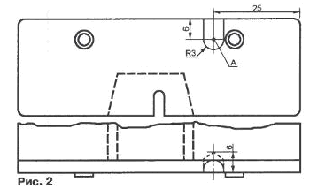
Although the unit is connected to the network in a transformerless circuit, due to the presence of a high-resistance resistor R10, when the high-voltage output closes to the ground, caused, for example, by touching the "chandelier", the current through the body of the touched will not exceed a few microamperes, which is completely safe. A small voltage drop across this resistor in the operating mode does not reduce the efficiency of the "chandelier". Since the current consumed by the unit from the network, and with it its power, is limited by the reactance of capacitors C1 ... C3 connected in parallel, the operation of the high voltage generator will stop when its output is closed. However, the energy accumulated in the capacitors of the voltage multiplier, the own capacitance of the "chandelier" and the wires leading to it will present some danger. But at a voltage of no more than 27 kV, this energy is relatively small, the electric shock will, of course, be noticeable, but not dangerous. The high voltage pulse generator is built on a VT2 transistor and a T1 transformer according to an inductive feedback circuit. The feedback winding (terminals 1', 2') is additional, it is wound with an insulated wire on a section of the ferrite magnetic circuit of the transformer free from other windings. The number of turns in it is selected experimentally. If there are less than ten of them, the operability of the generator after the elimination of the short circuit of the output is not automatically restored. You have to disconnect the device from the network for about a minute (until the capacitor C6 is completely discharged through the resistor R6) and turn it on again. At ten turns, it is no longer necessary to turn off the power, after 1 ... 3 s after the elimination of the short circuit, the generator starts to work, and at 15 turns there is no generation breakdown, only the output voltage decreases slightly. the pulses arriving at the base of the transistor VT2 from the auxiliary generator on the unijunction transistor VT1 make it easier to start the main generator. As you know, a positive voltage is supplied to the kinescope of a TV from a multiplier, and a negative voltage is needed to generate air ions. To get it, the voltage multiplier UNE / 27-1,3 should be finalized. First of all, it is necessary to remove the "~" and "F" leads, bury their remains into the multiplier case by at least 1 mm and fill it with sealant. The terminals, marked with the letter V and the body symbol, are connected together and soldered to them with a wire going to the resistor R10 and the "chandelier". The most difficult operation is to make the output "A" missing in the multiplier (in Fig. 1 it is shown by a thickened line). To get to the desired point, it is necessary, as shown in Fig. 2, carefully drill a hole approximately 6 mm deep in the bottom surface of the multiplier case, and then use a round file to expand it towards the rear surface. Having soldered the wire leading to the capacitor C9 to the exposed terminals of the capacitor and diodes, the hole is also filled with sealant, such as paraffin.
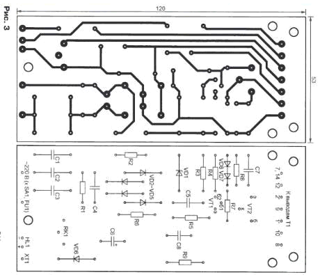
The printed circuit board, on which most of the device parts are located, is shown in Fig. 3.
Instead of diodes KD226D in the bridge rectifier, you can use KD105B, and instead of damping diodes of the same type (VD7, VD8) -KD411BM. The KT838A transistor can be replaced with a KT872A transistor, but you will have to make another heat sink for it. Capacitors (with the exception of oxide) - film. K73-17B. During normal operation of the generator, the amplitude of the voltage pulses between terminals 14 and 15 of the transformer T1 is about 9 kV, and the constant voltage at the output of the multiplier U1 is 25 ... 27 kV. In the absence of a kilovoltmeter, the operation of the generator can be checked by measuring the DC voltage at the test point with a conventional voltmeter. XT1 In nominal mode, it should be approximately 220 V. Another way to connect to the terminals 7 and 8 of the transformer according to the circuit shown in fig. 4, voltmeter PV1 - any multimeter in DC voltage measurement mode. It should show 6,3 ... 6,5 V.
Author: Alekseev A.
Artificial leather for touch emulation
15.04.2024 Petgugu Global cat litter
15.04.2024 The attractiveness of caring men
14.04.2024
▪ Ford Glare-Free Highbeam headlight system ▪ carbon dioxide from moist air ▪ Tests of the prototype Martian drilling rig ▪ Technology developed to extract water from the moon
▪ site section Welding equipment. Article selection ▪ article Mind for reason comes. Popular expression ▪ article Who is most likely to survive a nuclear war? Detailed answer ▪ article Aerosleigh Triumph. Personal transport ▪ article Phase presence indicator. Encyclopedia of radio electronics and electrical engineering
Comments on the article: Sergei Isn't the resistance R8 in the transistor circuit high, shouldn't it be on the order of 0.5-1 ohm? Viktor82 Cracks with a frequency of 400 Hz somewhere. This is fine?
Home page | Library | Articles | Website map | Site Reviews
www.diagram.com.ua |


 Leave your comment on this article: