|
|


 Arabic
 Bengali
 Chinese
 English
 French
 German
 Hebrew
 Hindi
Hindi Italian
 Japanese
 Korean
 Malay
Malay Polish
 Portuguese
 Spanish
 Turkish
 Ukrainian
 Vietnamese
|
ENCYCLOPEDIA OF RADIO ELECTRONICS AND ELECTRICAL ENGINEERING Voltage polarity switch for charger. Encyclopedia of radio electronics and electrical engineering
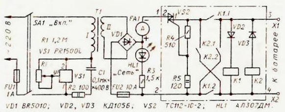
Encyclopedia of radio electronics and electrical engineering / Chargers, batteries, galvanic cells The device described below is designed to charge 12-volt automotive batteries. Its main feature is that that it allows you to connect the battery without thinking about its polarity. In a poorly lit garage, this is important, since the marking of the polarity of the charger clamps and the color of the connecting wires are often difficult to distinguish. The "Charger based on the PR1i power regulator" by S. Muralev, described in Radio 1500 No. 2009, p. 3, was taken as the basis for its design (see the schematic diagram in Fig. 40). in the figure, its scheme is highlighted by dash-dotted lines).
Since the principle of operation of the charger based on the PR1500i. its advantages and disadvantages are described in the article mentioned above, we will consider only the operation of the automatic switch. When the battery is not connected to terminals X1, X2, the triac VS2 is closed and the voltage at its output is zero. When the positive terminal of the battery being charged is connected to the X1 terminal of the charger, and the negative terminal to the X2 terminal, relay K1 is activated and a current will flow through the closed contacts K1.1 and K1.2 of the control electrode of the Triac VS2 and resistor R5, which will prepare the triac for opening. If you now turn on the charger in the network, the triac will open and the battery will start charging. If the battery is connected in reverse polarity, relay K2 will operate and by closing contacts K2.1 and K2.2 inverts the polarity of the charging voltage. The fuses FU1 and FU2 protect the charger from accidental short circuits of the load circuit. In both cases, even a short-term disconnection of any of the wires connecting the battery to the device will set the node to its original state, the triac VS2 will close on the last drop to zero half-wave voltage from the diode bridge VD1. As soon as the connection of the battery to the device is restored, the node will reconnect the load in the correct polarity. The machine uses a relay RP21 with a winding for a constant voltage of 12 V. It reliably operates even at a voltage of 8 V. Thus, the charger can work with a battery discharged to a voltage of at least 8 V, which satisfies most practical cases. It is better to turn on the charger in the network after connecting the battery and with the variable resistor R1 set to the position of the minimum charging current. The mains voltage supply is indicated by the HL1 LED. Then, resistor R1 sets the required charging current of the battery using ammeter PA1. The TT transformer must have a power of at least 80 W. The voltage of the secondary winding can be in the range from 14 to 20 V with a current through it of at least 5 A, an ammeter PA1 - any DC with a scale of 10 A. Resistor R1 - SP-I. It must be isolated from the body and provided with a plastic handle, since it will be under mains voltage. When assembling the charger, the triac VS2 and the diode assembly VD1 must be installed on heat sinks in the form of a duralumin or copper plate with a surface area of at least 16 cm. A properly assembled device does not need to be adjusted. If two RP21 relays could not be purchased, the machine can be assembled on one. The scheme of the automaton for such a case is shown in Fig. 2.
It is easy to see that when the battery is connected with a plus to terminal X1 (to terminal 3 of the machine), relay K1 remains de-energized, and when the polarity is reversed, it works and inverts the polarity of the charging voltage. It should only be borne in mind that the relay for this version of the machine must be with four groups of contacts. Author: Klemenov S.
Air trap for insects
01.05.2024 The threat of space debris to the Earth's magnetic field
01.05.2024 Solidification of bulk substances
30.04.2024
▪ Humanoid robot will go into space ▪ Artificial zipper removes odor from manure ▪ Concentration of thoughts hinders creativity
▪ section of the website Residual current devices. Selection of articles ▪ article by William Makepeace Thackeray. Famous aphorisms ▪ article What are crystals? Detailed answer ▪ Aloe article. Legends, cultivation, methods of application ▪ article ATX block for AT. Encyclopedia of radio electronics and electrical engineering
Home page | Library | Articles | Website map | Site Reviews
www.diagram.com.ua |


 Leave your comment on this article: