|
|


 Arabic
 Bengali
 Chinese
 English
 French
 German
 Hebrew
 Hindi
Hindi Italian
 Japanese
 Korean
 Malay
Malay Polish
 Portuguese
 Spanish
 Turkish
 Ukrainian
 Vietnamese
|
ENCYCLOPEDIA OF RADIO ELECTRONICS AND ELECTRICAL ENGINEERING Volume control with buffer stage. Encyclopedia of radio electronics and electrical engineering
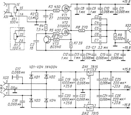
Encyclopedia of radio electronics and electrical engineering / Tone, volume controls At present, among many connoisseurs of high-quality sound reproduction, the so-called "ideology of a short path" finds its supporters. In such equipment, the preamplifier does not contain the usual tone controls, extra switching elements, loudness circuits and balance control, and most importantly, it contains a minimum of active components. Due to the fact that the output voltage of modern signal sources has actually become standard - 2 V, it is possible to abandon the pre-amplifier. However, the load capacity of such signal sources is not always sufficient for direct connection of a relatively low-impedance volume control or power amplifier. Therefore, in some cases it turns out to be useful to use a high-resistance volume control with a subsequent voltage follower, which acts as an interface between the regulator and the UMZCH input filter. Often such a cascade is built using a high-quality and expensive ORA627 op-amp in the voltage follower mode. In an op-amp with XNUMX% OOS, prerequisites are created for the occurrence of dynamic distortions. I conducted comparative listening of three buffer repeaters: the first - on the ORA627 op-amp, the second - on the ORA637 op-amp, the third - on field-effect transistors, described in the article. In the variant of the buffer stage using the OPA637 op-amp (this is the same OPA627, only adjusted for a gain of at least five), its gain is KU=5. This option showed, in the opinion of the author, a more transparent sound than with the OPA627, due to the limitation of the feedback depth and the expansion of the in-loop gain bandwidth in an amplifier less corrected than in the OPA627. The third option is a buffer based on a low-noise field-effect transistor, which is characterized by high linearity. This device was obtained as a result of a simplification of the headphone amplifier, proposed by the author on one of the forums several years ago and has proven itself well. Subjectively, such a buffer turns out to be the most "transparent", without any noticeable turbidity or specific colors in the sound. The type of repeater transistor and its operating mode were carefully selected, which made it possible to obtain very small non-linear distortions. Due to the fact that the transistor used is a microwave field effect transistor with a linear transfer characteristic and has small interelectrode capacitances, the non-linear distortions of such a follower at all audible audio frequencies remain very small. The buffer stage used here is designed mainly for UMZCH with an input resistance of at least 10 kOhm, while the THD at frequencies of 1 and 10 kHz at a voltage of 2 V is about 0,002%. The level of intrinsic noise of the cascade was not reliably measured by the author due to the lack of a voltmeter of true root-mean-square values. But when the repeater was connected to a spectrum analyzer (based on the SpectraLab program and the ESI Juli@ sound card), there was practically no shift in the bottom of the spectrum, and the noise level remained very low. Flicker noise, which is characteristic of insulated gate field-effect transistors, turned out to be imperceptible. The diagram of the volume control unit is shown in fig. 1.
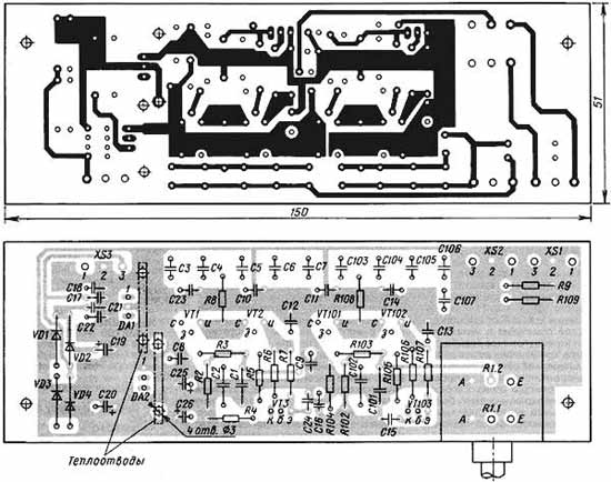
The input sound signal goes to a high-quality variable resistor of the volume control R1.1 (R1.2 - for another channel). Here, the use of a relatively high resistance resistor was dictated by the fact that it is a load for the signal source connected to the described block. The output stage of modern CD-DVD players, tape decks, sound cards, as a rule, is an integrated op-amp, the distortion of which is the lower, the higher the load resistance. Another important factor: even in relatively expensive models of CD-DVD players, tuners, computer sound cards, there are separating oxide capacitors at the outputs, and, as a rule, they turn out to be without polarizing voltage. Usually, for such purposes, oxide capacitors are chosen for a voltage of 63-100 V and a relatively low capacitance (typical value - 4,7 microfarads). In this case, the nonlinearity of the isolation capacitor will manifest itself the stronger, the lower the input resistance of the next stage. The need to coordinate the regulator node, both with the signal source and the subsequent UMZCH with parallel OOS, can be shown on the example of the ESI Juli@ sound card. As soon as this card became available on the Russian market, I read reviews on amateur radio forums, where they wrote that when the UMZCH was connected to the unbalanced outputs of the card, the bass was "liquid" and unnatural. When the load was connected to balanced "DC-coupled" outputs, this effect was not observed. It turns out that low-capacity tantalum capacitors are installed on the unbalanced outputs of the card. Therefore, with an input impedance of UMZCH of 10 kOhm, which is common for a broadband amplifier with parallel feedback, there was a lack of bass and some unnatural sound in the bass region. When UMZCH is connected through the described volume control unit with an input impedance of 100 kOhm, the above effect is no longer noticeable. Let's return to the description of the regulator assembly. From the engine of the variable resistor R1.1, the signal goes to the gate of the streaming repeater VT1, loaded with a current source, which is made on a transistor VT2 of the same type. A traditional bipolar transistor should not be used here due to the fact that its nonlinear collector capacitance is greater than that of 2P902; the linearity of the output resistance is also inferior to it. From the output of the stream repeater, the signal through a bunch of coupling capacitors C3-C7 enters the load. To obtain a deep and natural bass, the cutoff frequency of the HPF formed by coupling capacitors with an UMZCH input impedance (10 kOhm) was chosen very low - 0,95 Hz. As practice has shown, higher cutoff frequencies cause a feeling of "liquid" bass, devoid of "foundation" - despite the fact that, logically, a cutoff frequency of 10 Hz should be more than enough. The power supply of the device is made according to the traditional scheme and has no special features; it is advisable to use proprietary integrated stabilizers (µA7815UC, µA7915UC), since the noise level of other microcircuits may turn out to be non-normalized. Power is supplied from a step-down network transformer with windings for a voltage of 2x18 V and a load current of at least 150 mA. Structurally, the volume control is made on a printed circuit board made of fiberglass foiled on both sides, its drawing with the arrangement of elements is shown in fig. 2.
The numbering of the elements of the second channel starts from the second hundred (C101, VT101, etc.), the input and output of the second channel of the block are routed to pins 3 of the XS1 and XS2 connectors. The abundance of blocking capacitors, as well as the specific RF topology of the board (in some places, parallel connection of foil layers is used - for example, in the sources of VT1, VT2, and also between the source of VT1 and the drain of VT2) is dictated by the fact that 2P902A transistors are very prone to self-excitation at frequencies in the range DMV. Nuts should be screwed onto the body bolts VT1, VT2 until the threaded part is filled, they will perform the function of a heat sink (although the transistors heat up slightly even without nuts). The board is fixed to the front panel of the amplifier by means of two metal corners located on its sides. In the author's version, the volume control board was built into the case of the UMZCH itself, and to minimize possible interference from its high-current circuits, it was placed in a metal screen (rectangular box) made of tinplate, which is also fastened with two legs to the front panel of the UMZCH with bolts. The signal wires and the power supply wire pass through holes in the back wall of the shielding box. The author considered it inappropriate to make a separate case for such a volume control. In the volume control, it is possible to allow the replacement of some parts: the transistor 2P902A (VT1, VT2) - for KP902A, VS546 (VT3) - for KT3102AM, diodes 1N4004 (VD1-VD4) - for KD209A. Chips 7815 (DA1) and 7915 (DA2) can be replaced by their close counterparts. Chips of voltage stabilizers DA1, DA2 are installed on HS-315 heat sinks that have become popular with radio amateurs (sold in Chip iDip). Dual variable resistor (R1.1 and R1.2) - ALPS-RK27, purchased to order from SYMMETRON and DODEKA. C1, C2 - domestic ceramic capacitors KT-1, KD-2, K10-7V with TKE M47 and MZZ. All resistors used in the design are imported precision metal film (MF - Metal Film) with a power of 0,25 W. In the absence of such, domestic analogues of C2-29 can be used (in contrast to them, imported ones have leads without oxide), metal-dielectric C2-23, MLT (listed in descending order of preference). Capacitors C19, C20 - K50-35 or imported from Jamicon or Samsung; C25, C26 - K50-35 or similar imported ones; C8, C9, C12, C13 - EPCOS B32529-C105K for 63 V. They can be replaced with ceramic capacitors of a smaller capacity (at least 0,047 uF), for example, K10-7, KD-1, KM-5. Capacitors C3-C7 - EPCOS B32529-C5335 for 50 V with a capacity of 3,3 uF ± 5%; it is impossible to find a full-fledged domestic replacement here, because the used Epcos Staked MKT capacitors have not only a very high workmanship, but also an unprecedentedly high ratio of capacitance to dimensions, in other words, these capacitors are the most compact. Epcos capacitors are sold by companies known to radio amateurs. Capacitors C10, C11, C14-C16, C21-C24 - K10-7V with a capacity of 0,068 uF at 40 V. XS1-XS3 connectors - DINKLE-DT126VP terminal blocks. In conclusion, it is useful to give some recommendations on the installation of KP902 transistors. These devices are extremely "gentle", they cannot withstand exceeding the permissible voltage: at a drain-source voltage of more than 50 V, such a transistor breaks through; dangerous for him and static electricity. But the main insidiousness lies in the fact that in these devices it is possible to "knock out the shutter"; in this case, the transistor remains operational, but leakage in the gate circuit and noise increase. In order to avoid trouble, the installation of devices should be carried out using an antistatic soldering station or turn off the mains soldering iron during soldering and use an antistatic wrist strap. Otherwise, as practice has shown, the failure of transistors is almost guaranteed. Therefore, when buying KP902A, you need to pay attention to the storage conditions for these devices; in stores they are usually sold packaged in foil. After assembling the board, it is useful to check the health of the transistor VT1; to do this, you need to bring the R1 controls to the maximum volume position, and connect a high-resistance DC millivoltmeter to the input. If a small constant voltage is present on the resistor R1, then this indicates that VT1 has a “gate knocked out”. Author: Ya. Tokarev, Moscow; Publication: cxem.net
Energy from space for Starship
08.05.2024 New method for creating powerful batteries
08.05.2024 Alcohol content of warm beer
07.05.2024
▪ Ultra-budget smartphone Infinix Smart 7 HD ▪ Evaporation chambers in smartphone cooling systems
▪ section of the site Dosimeters. Selection of articles ▪ article Than people are alive. Popular expression ▪ article What is a dividend? Detailed answer ▪ article Driver of a mobile compressor (station). Standard instruction on labor protection ▪ article Forgotten Radiometeorology. Encyclopedia of radio electronics and electrical engineering ▪ article Invulnerable paper. Focus Secret
Home page | Library | Articles | Website map | Site Reviews
www.diagram.com.ua |

 Leave your comment on this article: