|
|


 Arabic
 Bengali
 Chinese
 English
 French
 German
 Hebrew
 Hindi
Hindi Italian
 Japanese
 Korean
 Malay
Malay Polish
 Portuguese
 Spanish
 Turkish
 Ukrainian
 Vietnamese
|
ENCYCLOPEDIA OF RADIO ELECTRONICS AND ELECTRICAL ENGINEERING Protection of power supplies from lightning. Encyclopedia of radio electronics and electrical engineering
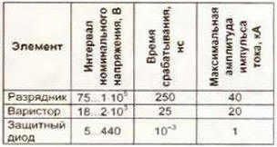
Encyclopedia of radio electronics and electrical engineering / Protection of equipment from emergency operation of the network In order to protect the equipment from impulses induced by lightning discharges, the power supply to telecommunications and security devices, as well as to video surveillance systems, where it cannot be turned off due to operating conditions, is carried out in accordance with the requirements and, as a rule, uninterruptible power supplies with built-in network protection devices. But what about those who, for example, leave switched on equipment in their dacha that notifies the owner of the penetration of unauthorized persons into the controlled territory? In order to reduce the likelihood of damage to the security device during a thunderstorm, its power supply must be supplemented with some elements that sharply attenuate high voltage pulses in the network, which we will further call network interference. The effectiveness of suppression of such interference by the same elements is different. This implies the first feature - the protective device must be multi-stage The second feature of the design of a protective device is the need for a conductor with zero potential, "ground", in it. This condition is easy to meet in modern apartments where the wiring is made according to a three-wire circuit ("phase" (L), "zero" (N), "protective earth" (PE)). If the supply network is without protective grounding, then you will either have to create a ground loop yourself, or come to terms with it. that interference suppression will not be effective enough. It is satisfactory if the interference from the phase wire is diverted to zero, it is good - from the phase wire and separately from the neutral wire to the ground wire is excellent - from the phase wire separately to the neutral wire and to the ground wire, and also from the neutral wire to the ground wire. To attenuate long-term powerful interference generated by lightning discharges, vacuum and gas-filled spark gaps are used as pulse energy absorbers. According to statistics, the share of such interference is approximately 20%. The remaining 80% are short-term, which are effectively suppressed by capacitors parallel to the protected circuit and series barrier elements - chokes. A combined method is also used, when powerful interference is attenuated by absorbing elements (voltage limiters) connected in parallel, and low-power ones are reduced in series. The generalized characteristics of the most common voltage suppressors used in protective devices are presented in the table:
Gas-filled arresters can be used in two- and three-electrode versions, depending on the design of the protective device - two-wire or three-wire. In terms of reliability of operation and maximum pulse current, such a voltage limiter surpasses all others (Fig. 1). This is a cylindrical container with discharge electrodes at its ends, filled with an inert gas. The disadvantage of the arrester is its slower response compared to other protective elements, which is due to the need for a certain time interval for gas ionization.
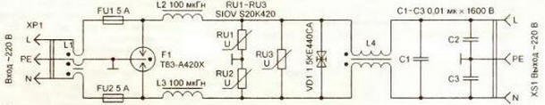
Consider a three-electrode spark gap T23-A230X with a diameter of 8 and a length of 10 mm. Despite such a small size, this protective element allows a peak discharge current in multiple single pulses 8/20 μs (front/fall) up to 20 kA or withstands an alternating discharge current of 1, and a frequency of 10 Hz for 50 s. Such protection efficiency is ensured by the special design of the arrester, which is illustrated in Fig. 1. In the initial state, its resistance exceeds 10 ohms. When the voltage in the discharge gap creates an electric field strength capable of causing gas ionization, an electric discharge occurs, as a result of which the resistance of the spark gap decreases sharply. At the end of the pulse, the inert gas regains its insulating properties. The breakdown voltage of the discharge gap is determined both by the size and design of the electrodes and by the properties of the filling gas - composition and pressure. A special compound coating of the electrodes and a ceramic insulator between them activates their emissivity. The ring shape of the central electrode makes it possible to maximize the use of the surface of the end electrodes 1 and 2, providing a large discharge current without erosion of the current-carrying surfaces. In order to compensate for the delay in operation from interference with a steep front (1 kV/μs or more), the arresters in multistage protective devices are usually supplemented with varistors and protective diodes, which divert some of the energy of the impulse noise at the initial moment of its appearance in the electrical network . A metal oxide varistor is similar to a symmetrical zener diode - when a certain threshold value of the applied voltage is exceeded, the resistance of the element drops sharply. The classification voltage of the varistor must exceed the maximum amplitude of the mains voltage by at least 5%. For example, the maximum allowable increase in the mains voltage of 220 V by 20% (264 V) corresponds to an amplitude of 374 V. Therefore, the classification voltage of the varistor must be at least 393 V. If you use a varistor, as in many industrially manufactured protective devices, with a standard classification voltage of 390 B, due to the permissible technological error of this parameter, there is a risk of its damage. Therefore, it is better to use it with a slightly higher classification voltage. The varistor is also characterized by a certain limiting pulse energy, which it can absorb without destruction. This characteristic has the property of accumulation. This means that the device is able to absorb a single pulse with a certain maximum allowable energy or a certain number of pulses with a lower energy without degrading the parameters. For example, a metal oxide varistor with a diameter of 20 mm absorbs a pulse with a maximum allowable energy of 410 J or 10 pulses with an energy of 40 J. After the varistor runs out of the pledged resource, its classification voltage will increase slightly, and then with each subsequent pulse it will begin to decrease sharply, as a result, the varistor will "burn out" . Therefore, it must be replaced at the slightest external manifestation of degradation (darkening of the paintwork). The need to monitor the technical condition of the variator located inside a closed network filter is its disadvantage. Protective diodes (Transient Voltage Suppressor), like zener diodes, become conductive extremely quickly when the applied voltage increases above the opening voltage. The response time of such a device, especially a leadless one, is only a few picoseconds. Of course, the inductance of the leads and lead wires reduces the speed of the diode, but nevertheless it remains the highest among the voltage limiters used. There are both unipolar protective diodes and those with a symmetrical current-voltage characteristic, which allows them to be used without additional rectifying diodes in AC circuits. At a very high current, in contrast to a gas-filled spark gap, the electrical breakdown occurring in the protective diode becomes irreversible. This element must be replaced. Industrially manufactured devices for protection against high-voltage impulses in the power grid, both in our country and abroad, must comply with the requirements of international standards approved. International Electrotechnical Commission (IEC), and according to generally accepted terminology are divided into I, II and III protection classes. Class I devices are designed to protect the electrical network at the entrance to the building in front of the electricity meter. The main elements of such devices are vacuum and gas-filled arresters capable of neutralizing powerful lightning discharges up to 150 kA per pulse, which corresponds to a direct lightning strike, taking into account the current spreading over the surface subjected to an electric shock. Class II devices attenuate impulse noise in storey and workshop switchboards. The most commonly used protective element in such devices is the varistor. Class III devices are designed to protect individual devices with a current consumption of not more than 16 A. They are usually performed on protective diodes. Of course, for the safe operation of radio equipment, the user can equip the power distribution network in a country house or apartment with such industrial devices, but the implementation of such a solution may be financially difficult. It will be much cheaper to independently manufacture network protective devices. Based on the analysis of modern ideas about the requirements for lightning protection devices and methods for their practical implementation, the author has developed a multi-stage protective device, the diagram of which is shown in fig. 2.
The device is connected to the network using an electrical plug. XP1 with grounding contact. Fuse-links FU1, FU2 are designed for a load of up to 1 kW, connected to the socket XS1, their presence significantly increases the reliability of the protective device and extends the life of other elements used in it. Short-term interference, unable to trigger the arrester F1, will be weakened by the chokes L2-L4 and absorbed by the protective diode VD1. A significant contribution to the attenuation of such interference is also made by a ferrite cylinder worn on the network cable, as a result of which an inductor L1 is formed. Capacitor C1 finally suppresses symmetrical short-term mains interference, unbalanced - C2 and C3. The suppression of the front of continuous network interference generated by lightning discharges occurs primarily by the protective diode VD1 and varistors RU1-RU3. After 250 ns, the switched-on spark gap F1 removes the interference to itself, and the triggered fuses FU1, FU2 disconnect the power supply of the equipment from the mains until critical consequences occur. The energy of impulse noise dissipated by the protective elements in the network filter is released in the form of heat, while the temperature of the elements can reach 200 ° C or more. Therefore, for reasons of fire safety, the body of the device must be made only of metal. Connecting the housing to the wire from the grounding contact of the plug. XP1 is performed in the immediate vicinity of the input of the network cable into the filter housing. The socket XS1 is connected by short wires to the corresponding pads indicated on the drawing of the printed circuit board of the device (Fig. 3).
A photo of the board is shown in fig. four.
The printed circuit board is made of one-sided foil fiberglass 1,5 mm thick. The grounding protective elements of the printed conductor on the board are peeled with solder to increase the cross-sectional area, creating a roller 1 ... 1,5 mm high. The network cable is used with wires with a cross section of at least 1 mm2. A ferrite cylinder is put on it. K18 * 9x30 mm (shown on the left in Fig. 4). Foreign manufacturers install such cylinders on cables to connect various devices to a computer. Inductors L2 and L3 are wound with PEV-2 wire with a diameter of 1 mm each on two annular magnetic cores folded together. KP27>15-6mm from MP 140 permalloy. Winding is performed in two full layers without interlayer insulation, the author used ready-made chokes coated with enamel for moisture protection. You can also use a magnetic circuit. K28>14-12mm from a multi-winding choke in an AT switching power supply of a computer. Choke L4 is performed on a K28-15-10mm ring made of M2000NM ferrite. The sharp edges of the magnetic circuit are rounded off with a file, and then insulated with varnished cloth or fluoroplastic tape. Each of the windings contains 15 turns of wire. PEV-2 with a diameter of 1 mm, for design reasons, for the convenience of connecting the leads to the printed circuit board, one of the windings is wound in the direction opposite to that used for the other winding. In this case, the fields created by the incoming and outgoing currents in the magnetic circuit will be mutually compensated and magnetic saturation is thereby excluded. The correct execution of the inductor can be checked by measuring its inductance. In this design, the inductance of each winding is 270 µH. If you connect the output ends of the windings and measure the input inductance, it will not exceed 10 μH. Varistors RU1-RU3 - SIOV S20K420. they can be replaced by other metal oxide ones with a diameter of 20 mm and a classification voltage of 420 V. In extreme cases, you can use zinc oxide of the same diameter with a classification voltage of 430 V, marked, for example, by one of the manufacturers as MYG20K431. High-voltage capacitors C1 - C3 - from the K78-2 series. The 1,5KE440CA symmetrical protective diode can be replaced by two of the same unipolar ones (without the CA index) or their analogues. In this case, it is advisable to supplement the protective device with an indicator of the mains voltage and the health of the protective diodes. During the operation of the device, it is necessary periodically, especially after thunderstorm days, to monitor the technical condition of the device and replace the elements that have exhausted their resource in a timely manner. Author: Kosenko S.
Machine for thinning flowers in gardens
02.05.2024 Advanced Infrared Microscope
02.05.2024 Air trap for insects
01.05.2024
▪ Effective antimicrobial film for gadgets ▪ All the most valuable companies in the world are from the IT sector ▪ Monkeys are capable of long reflections ▪ Iogear GTD733 Docking Station
▪ section of the site Art video. Article selection ▪ article Under the fly (to be). Popular expression ▪ article Which American woman married the president without changing her last name? Detailed answer ▪ article Chip driver. Standard instruction on labor protection ▪ article Voltage converter for LED lamp. Encyclopedia of radio electronics and electrical engineering ▪ article A vase on... a lathe. Encyclopedia of radio electronics and electrical engineering
Home page | Library | Articles | Website map | Site Reviews
www.diagram.com.ua |


 Leave your comment on this article: