|
|


 Arabic
 Bengali
 Chinese
 English
 French
 German
 Hebrew
 Hindi
Hindi Italian
 Japanese
 Korean
 Malay
Malay Polish
 Portuguese
 Spanish
 Turkish
 Ukrainian
 Vietnamese
|
ENCYCLOPEDIA OF RADIO ELECTRONICS AND ELECTRICAL ENGINEERING Tesla transformer - varieties, experiments. Encyclopedia of radio electronics and electrical engineering
Encyclopedia of radio electronics and electrical engineering / Power Supplies VTTC owe their appearance to the invention and dissemination of high-power oscillating electronic tubes capable of creating electromagnetic oscillations with a power of hundreds and thousands of watts. Unlike spark generators, which create repetitive bursts of damped high-frequency oscillations, tube generators are capable of generating a continuous signal, which, if necessary, can be modulated in amplitude. These are classic tube oscillators, the load of which is the primary winding of the Tesla transformer. Such devices are popular among foreign and domestic hobbyists, although to a lesser extent than SGTC. The main difficulties in their creation are the large size of powerful generator lamps, the need for their air or even water cooling and high-voltage anode power supply. Consider the one shown in Fig. 9 diagram of a Tesla tube transformer on modern components. This is a classic generator with inductive (transformer) feedback. The VL1 lamp (GK-71 pentode, widely used in amateur radio transmitters) is turned on by a triode - all its grids are connected together. Pentode switching, which reduces the capacitance of the lamp and reduces the likelihood of its self-excitation, in this case has no advantages, since it is self-excitation that is required.
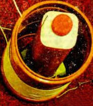
The anode load of the lamp is an oscillatory circuit formed by the winding I of the transformer. T3 and capacitor C2. Next to this winding on the same frame is the feedback winding II. The voltage induced on it is supplied to the grids of the lamp, providing the necessary positive feedback for generation. The variable component of the grid current is closed to the cathode through the capacitor C4, and the constant, flowing through the resistor R1, creates a voltage drop across it, applied by the minus to the grids of the lamp. This is the automatic bias voltage. Increasing in absolute value, it partially closes the lamp with an increase in the amplitude of the high-frequency signal, and when it decreases, it also decreases, which leads to an increase in amplitude. In this way, the oscillation amplitude is kept constant. By selecting the resistor R1, it is possible to regulate the power of the generator within certain limits. Blocking capacitors C1 and C3 minimize the penetration of high-frequency voltage into the mains supply. The voltage source supplied to the anode of the lamp VL1 consists of a transformer T1 from the kitchen. Microwave oven and half-wave rectifier connected in series with diodes VD1-VD4. The maximum value of the voltage pulsing with a frequency of 50 Hz at the output of the rectifier is about 3 kV. The signal of the generator fed by such a voltage has the form of flashes of high-frequency oscillations following with a pulsation frequency. This somewhat facilitates the operation of the lamp (a voltage of 3 kV is higher than that allowed for it in continuous mode) and favorably affects the number and shape of the observed discharges. The filament voltage is supplied to the lamp VL1 from the transformer T2. It is important to note that the device must be turned on in two stages. First of all, the SA2 switch turns on the glow. and only after a few tens of seconds, when the cathode of the lamp warms up, the anode voltage is applied, closing the SA1 switch. By connecting the transformer T1 to the network through an adjustable autotransformer (LATR), you can smoothly increase the anode voltage when turned on and adjust it during the experiments. The design of the transformer T3 is shown in fig. 10. Windings I and II are wound on a piece of plastic plumbing pipe with a diameter of 160 mm. Winding I consists of 30 turns of insulated wire with a cross section of 4 mm. Winding II contains 20 turns of enameled wire with a diameter of 0,22 mm. The output winding (III) is the same. as in previous cases, wound on a bottle of kefir.
In the absence of the GK-71 lamp, you can use the less powerful GU-50, as well as the 6P36S, 6P45S lamps used in horizontal scanning of TVs. To increase the power, such lamps can be connected in parallel. Do not forget to also select a T2 transformer with a voltage on the secondary winding corresponding to the rated filament voltage of the lamp used. The oscillatory circuit in the anode circuit of the VL1 lamp must be tuned to the resonant frequency of the winding III of the T3 transformer. To do this, measure the inductance of the winding I and calculate the capacitance using a known formula. Capacitor C2 must be high-voltage, for example, KVI-3. Good results are obtained by using a vacuum variable capacitor. If it is not possible to measure the inductance, several taps can be made from the winding I and the optimal number of turns in it can be selected according to the longest length of the resulting discharges. it makes sense to provide for the possibility of moving winding II relative to winding I in order to select the optimal feedback coefficient. Just as in the previous case, it should be remembered that the device contains elements that are under life-threatening voltage. Any touch to it while the power is on is unacceptable. All adjustment and refinement of the device can be made only after it is disconnected from the network and the forced discharge of all high-voltage capacitors. In general, it can be noted that compared to SGTC, VTTC operates somewhat "softer", and its design is more convenient due to the absence of a spark gap that gradually burns and requires adjustment. it is interesting to note that the discharges are not like those. that were obtained using SGTC. The spiral shape of the streamers is quite unexpected (Fig. 11), the reason for this is unknown to the author.
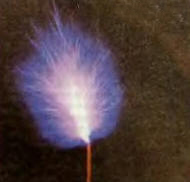
To compare the shape of the discharges at pulsating and constant anode voltage, the half-wave rectifier of the anode voltage was replaced by a full-wave (diode bridge) and a large-capacity smoothing capacitor was added. The result is shown in fig. 12.
The differences are clearly visible. With the high frequency voltage generated by the flashes, each streamer only lasts half a cycle of mains voltage. The new discharge does not follow the path of the old one, but rushes to another place. We see several long single streamers. With continuous generation, the resulting "torch" burns constantly. It is very similar to an ordinary flame and even deviates if you blow on it. However, in still air, the torch is not directed strictly upwards, like an ordinary flame, but at a certain angle to the vertical. Perhaps this is due to the structure of the magnetic field around the transformer. The difference in the modes is also clearly noticeable by ear: in a pulsating one, a loud hum with a frequency of 50 Hz is heard, and in a continuous one - only a slight hiss. Theoretically, you can use a Tesla transformer as a sound source if you modulate the generator with an audio signal. In fact, you get an AM transmitter operating at the resonant frequency of the Tesla transformer. An interesting experiment was carried out with an "ion engine" - a spinner made of electrically conductive material placed on the tip of the output electrode of a Tesla transformer. Streams of ionized particles, flying off the sharp curved ends of the blades of the spinner in one direction, create a jet thrust that sets it in motion. For good results, the turntable should be light and well balanced. To take the photograph shown in Fig. 13, the anode voltage on the VL1 lamp had to be reduced to 1000 V. otherwise the rotation turned out to be too fast and the turntable often fell.
It should be noted that despite the 100-year history, the Tesla transformer has not yet been fully studied. For example, the author failed to find an explanation for the spiral shape of streamers, methods for accurately calculating the input resistance of the Tesla transformer and its exact matching with the generator, methods for calculating the length of the discharges and the effect of their own capacitance on the resonant frequency of the transformer. Apparently, these problems have been little studied and practically not covered in the available sources. In general, the Tesla transformer is a very extensive and not fully explored field for experiments. Among amateurs, there is even an opinion that the efficiency of a Tesla transformer exceeds 100%. because it draws "free energy" from space. This. of course. far from it. No violations of the law of conservation of energy were observed during experiments with Tesla transformers. As mentioned above, the Tesla transformer is a fairly powerful source of electromagnetic radiation. Therefore, it was interesting to evaluate its possible impact on other electronic devices. For experiments, a Tesla transformer with a vacuum tube generator grounded to the neutral wire of the electrical network was used. The following was noted:
Thus, the author did not notice a particularly dangerous effect on consumer electronic devices. However, when conducting experiments, it is still recommended to exercise reasonable caution. For example, it makes sense to physically disconnect expensive equipment from the network for the duration of the experiments. It is also recommended to disconnect all antennas and long cables connecting the electronic units. If possible, a separate ground should be used for the Tesla transformer. Although there are descriptions of Tesla transformers on the Internet with a discharge length of more than half a meter, the author would not recommend making and running them at home. Author: Elyuseev D.
Machine for thinning flowers in gardens
02.05.2024 Advanced Infrared Microscope
02.05.2024 Air trap for insects
01.05.2024
▪ Chickens talk about geographical discoveries ▪ Predatory bacteria as a living antibiotic ▪ Sony MDR-HW9.1DS 700 Wireless Headphones
▪ site section Voltage converters, rectifiers, inverters. Article selection ▪ article Corruption of morals. Popular expression ▪ article What type of garbage do city birds scare away parasites in their nests? Detailed answer ▪ article Linear pipeline. Standard instruction on labor protection ▪ article Relay control at low voltage. Encyclopedia of radio electronics and electrical engineering ▪ article Amateur radiotelephone RTF-92. Encyclopedia of radio electronics and electrical engineering
Home page | Library | Articles | Website map | Site Reviews
www.diagram.com.ua |


 Leave your comment on this article: