|
|


 Arabic
 Bengali
 Chinese
 English
 French
 German
 Hebrew
 Hindi
Hindi Italian
 Japanese
 Korean
 Malay
Malay Polish
 Portuguese
 Spanish
 Turkish
 Ukrainian
 Vietnamese
|
ENCYCLOPEDIA OF RADIO ELECTRONICS AND ELECTRICAL ENGINEERING A simple self-generating SMPS with a power of 1,5 kW for UMZCH. Encyclopedia of radio electronics and electrical engineering
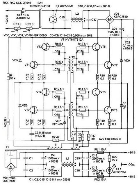
Encyclopedia of radio electronics and electrical engineering / Power Supplies The development of the proposed SMPS was carried out on the basis of the prototype described in the article by E. Gaino and E. Moskatov "Powerful switching power supply" in "Radio", 2004, No. 9, p. 31, 32. A tentative goal was to increase the power output by a factor of three while maintaining the principle of operation and low cost of the product due to the use of widely used components. that is why preference was given to controlling the switching transistors with a saturable transformer. The device uses resistors in the positive feedback circuit instead of using a driver chip with numerous "strapping" components. In addition, the base current of bipolar switching transistors is many times higher than the maximum allowable output current of modern driver microcircuits, such as IR2110, IR2113 and similar. This requires the introduction of an amplifying matching stage and an auxiliary source for its power supply to match the microcircuit with transistors, which negates such an advantage of the proposed SMPS as a small number of components. Instead of cheap and common bipolar transistors, powerful MOSFETs or IGBTs could be used, but then another advantage would disappear - the low cost of components. The prototype conversion frequency at no load is only 9 kHz, so its pulse transformer is heavy and emits an unpleasant whistle. The proposed SMPS does not have such a drawback, since its minimum conversion frequency is 30 kHz. The scheme of the proposed IIP is shown in the figure. The basis of the SMPS is a self-generating bridge voltage converter with a non-saturable high-power transformer T1 and a saturable low-power transformer T2, the use of such converters is a well-known and widespread solution, it is used in "electronic transformers", ballasts of energy-saving lamps and other devices, however, these devices are of lower power according to compared to what is offered.
Main technical characteristics:
Due to the fact that the UMZCH has its own current protection, there is no need for this function in the SMPS. The conversion frequency is not constant - it is the higher, the greater the load power. Thermistors RK1 and RK2 limit the starting charging current of the oxide capacitor C21 when connected to the network. To de-energize the device in case of an accident, an automatic switch SF1 is designed. The gas arrester F1 protects the device from power overloads. on capacitors. C10, C17 and two-winding choke L2, a U-shaped filter is assembled to prevent the penetration of high-frequency interference from the SMPS into the network. The diode bridge VD8 rectifies the alternating voltage of the network, and the capacitor C21 smooths it out, the capacitor C22 shunts the output of the rectifier at a high frequency. A relaxation oscillator is assembled on resistors R1, R2, R7, capacitor C3 and dinistor VD7, which generates the pulses necessary to start the generator after turning on the power, as well as restore the conditions for the generation to occur after its failure. Resistors R8-R15 limit the base current of switching transistors VT1-VT8, capacitors C6-C9, C11-C14 accelerate their switching. Diodes VD5, VD6, VD9, VD10 dampen transient voltage surges. Resistors R3-R6, R18-R21 in the emitter circuits of transistors equalize the current flowing through them. Capacitor C20 eliminates the magnetization of the magnetic circuit of the non-saturable transformer T1 with direct current. Through resistors R16, R17, a positive feedback circuit is formed from the output of the converter (from winding III of transformer T1) to its input (winding V of transformer T2). The resistance of these resistors, the number of turns of the windings, the dimensions and magnetic properties of the material of the magnetic circuit of the saturable transformer T2 determine the conversion frequency, which can be calculated by the formula:
where F is the conversion frequency, kHz; U is the amplitude of the voltage pulses on the winding V of the transformer T2, V; Vnas - saturation induction of the switching transformer T2, T; q is the duty cycle of the pulses; Sc - cross-sectional area of the magnetic circuit of the transformer T2, cm2; W is the number of turns of the winding V of the transformer T2; K - the fill factor of the magnetic circuit of the transformer T2, for ferrite almost reaching unity. The diode bridge VD1-VD4 rectifies the impulse voltage of the winding I of the transformer T1. Capacitors C1, C2, C4, C5, C15, C16, C18, C19 and a two-winding inductor L1 smooth out high-frequency and low-frequency output voltage ripples. Fuses FU1 and FU2 provide protection against a slow increase in load current in excess of the allowable limit. LED HL1 - indicator of the operating status of the device, resistor R22 - current limiting. The design of the SMPS is arbitrary, the mutual arrangement of the components is not critical, although it is desirable that each of the diodes VD5, VD6, VD9, VD10 be placed as close as possible to its pair of transistors VT1VT3, VT2VT4, VT5VT7, VT6VT8. the source is assembled by hanging installation. Automatic switch А-0701НМ (SF1) manufactured by Sang. Mao Enterprise Co., Ltd., for breaking current 15A and rated voltage 250V, can be replaced by A-0702A, A-0702X, A-0710W, CBLS2A15, M115-B120. The SCK-2R515 thermistors (RK1 and RK2) can be replaced with MS32 5R020, MS32 7R015 or similar NTC thermistors with a maximum current carrying capacity of at least 15 A and a nominal resistance of 5 to 10 ohms at 25°C. The key power switch TR26-21C-11D1 (SA1) can be replaced with SWR74 or a switch with illumination MK-521A/N. Gas arrester 2027-35-C (F1) can be replaced by B88069-X2380-S102, B88069-X370-S102, B88069-X410, FS04X-1JOS or FS04X-1JMG. Instead of 30ETH06 (VD1 - VD4), diodes 80E8U04, DSEI30-06A, HFA25TB60, RHRG3060 are suitable. Each diode is mounted on a separate heat sink with a cooling surface area of 90 cm2. Diodes HER1608G (VD5, VD6, VD9, VD10) are interchangeable with 15ETH06, 15ETX06S, HFA25TB60, DSEI12-06A, FES16JT, and the diode bridge. KVRS2510 (it must be equipped with a heat sink with a usable area of at least 50 cm2) - any of the GBU25M. BR2510, BR2510W, KVRS3510 or MB4010. Dinistor VD7 - any of KN102A - KN102V and 2N102A - 2N102V; the last three are preferred for SMPS operation at elevated temperatures. Also suitable are imported dinistors DB-3 or D8-4 with a switching voltage of 32 and 40 V, respectively. Switching bipolar transistors VT1-VT8 are each installed on a heat sink with a cooling surface area of 140 cm2. Instead of KT812A, you can use eight of the same type of transistors 2T812A, KT812B or KT840A. Capacitors C1-C3, C15, C16, C22 are polyethylene terephthalate MER or MEF, and C20 is composed of eight parallel-connected MER capacitors of 1 microfarad each with a rated voltage of 630 V. Capacitors C6-C9, C11-C14 are ceramic. KM5B-N90, K10-17A-N50 K10-17B-N50. Capacitors. SU and S17 - V32923-A2474M, designed for connection to the AC mains. it is permissible to replace them with capacitors 881131-C 1105-M, B81131-C1474-M, B81141-C1684-M. B81141-C1334-M or equivalent. Oxide capacitors C4, C5, C18, C19, C21 - aluminum K50-6 K50-35 or similar. All fixed resistors used in the power supply are non-wire, for example, MLT, OMLT, S2-23, S2-33. Resistors R1, R2 and R22 must have a rated power dissipation of 2W. Resistors R3-R6, R18-R21 are imported ceramic CRL series, they can also be composed of several resistors connected in parallel to obtain the required resistance and dissipation power. The pulse transformer T1 is made on a magnetic circuit of size Ш20х28 made of ferrite. M2000NM-9, corresponding to the specifications OZHO.707.140TU. It is also permissible to use M2000NM1-17 ferrite. Winding I of this transformer contains 2 sections of 8 turns of a bundle of four PETV-2 0,5 wires folded together. Winding II contains 28 turns of two PETV-2 0,5 wires folded together, and winding III contains one turn of PEV-2 0,5 wire. All windings must be securely isolated from one another with fluoroplastic, mylar or varnished fabric tape. Transformer T2 is wound on an annular ferrite magnetic circuit of size K6xXNUMXxXNUMX from a self-oscillating electronic ballast of an energy-saving lamp. Each of the I-IV windings contains four turns of PEV-2 0,25 wire, and the V winding contains nine turns of PEV-2 0,5 wire. Choke L1 - homemade. It is made on an annular magnetic circuit, composed of two identical parts of the standard size. KP35x26x7, from alsifer brand. PM-60. Windings I and II are wound in two PEV-2 2 wires until the window is filled. Instead of PEV-2, you can use the PETV wire. Inductor L2 - ready-made B82726-S2163-N30, which, according to the passport, allows a winding current of 16 A at a maximum voltage between them of 250 V. The inductance of each winding is 2,2 mH. Fuses FU1 and FU2 - H630PT-15A H630-15A or similar. LED HL1 - any, preferably green glow. The SMPS assembled from serviceable parts should start working immediately after switching on. If there is no autogeeration, you need to check the phasing of the windings of the transformer T2 and, possibly, swap the connection of the terminals of its winding V or winding III of the transformer T1. If the conversion frequency without load is significantly different from 30 kHz, this indicates an unsuitable material or a defect in the magnetic circuit of the transformer T2, such as a hidden crack. In this case, the magnetic circuit must be replaced. Author: D. Butov, p. Kurba, Yaroslavl region
Machine for thinning flowers in gardens
02.05.2024 Advanced Infrared Microscope
02.05.2024 Air trap for insects
01.05.2024
▪ SONY and TOSHIBA disagree on video format ▪ Synthesized a new form of carbon
▪ section of the site Note to the student. Article selection ▪ Almighty dollar article. Popular expression ▪ article What fires in ancient times were extinguished with milk? Detailed answer ▪ Article Glod. Legends, cultivation, methods of application ▪ article 60Hz Clock Power Converter. Encyclopedia of radio electronics and electrical engineering
Home page | Library | Articles | Website map | Site Reviews
www.diagram.com.ua |


 Leave your comment on this article: