|
|
ENCYCLOPEDIA OF RADIO ELECTRONICS AND ELECTRICAL ENGINEERING The simplest circuits of single-cycle converters. Encyclopedia of radio electronics and electrical engineering
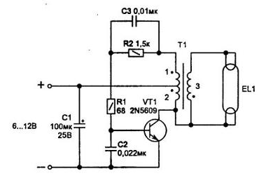
Encyclopedia of radio electronics and electrical engineering / Voltage converters, rectifiers, inverters On fig. 4.7-4.9 are fairly simple circuits that are often used to power a stroboscopic or low-power fluorescent lamp in designs where there are no high requirements for parameters, and the main thing is low price. Such devices can find many other uses, for example, as a primary boost converter for an electroshock device. They allow you to get 3 V or more from a constant voltage of 15 ... 400 V. The simplest converter can be performed according to a single-act circuit. Its principle of operation is based on the property of inductance to accumulate energy when current flows through the winding (when the key is open), and when the key is closed, it is transferred to the load through the secondary winding. This mode of operation of the circuit is provided with appropriate phrasing of the inclusion of the secondary winding. Due to the operation of the converter at an increased frequency, the design of the transformer is small-sized. On fig. 4.7 shows a diagram of a converter made on one powerful universal transistor 2N3055 (domestic counterparts KT819GM, KT8150A). Other powerful npn transistors with a permissible voltage Uke> 80 V and current Ik> 2 A are also suitable. Diode VD1 protects the emitter-base junction of the transistor from the effects of a large reverse voltage. This diode must be fast, for example, from the 1N4007 or KD247 series. The 1N4S4S diode can be replaced by two KD257D diodes connected in series.
In the circuit, you can use a transistor and other conductivity. You only need to change the polarity of the voltage supply and turn on the diode VD1. Resistor R1 provides the desired position of the operating point of the transistor and its value must be selected. Resistor R2 limits the current of diode VD2 when charging capacitor C3. Capacitor C2 is suitable for any non-polar (the operating frequency of the converter depends on it). It is better to choose a frequency of at least 10 ... 30 kHz. And if the circuit will work with a strobe lamp, capacitor C3 must be designed for long-term operation with large current ripples, for example, of the MBM type or take more modern ones made on the basis of a polystyrene film. K78-17, K71-7 etc. For the manufacture of transformer T1, an armored magnetic circuit BZO is suitable. Winding is done with PEL wire. Windings 1 and 2 each contain 18 turns of wire with a diameter of 0,51 mm (winding 1 can be made with a thinner wire - 0,13 mm), 3 - 350 turns of wire 0,13 mm (the number of turns in the secondary winding depends on the required voltage ). If the circuit is required to work for a long time, the transistor VT1 must be installed on a radiator. The scheme shown in fig. 4.8 is a variant of the previous one. It is designed to power a small-sized portable fluorescent lamp from 8 AA batteries).
Transformer T1 has the following winding data: winding 1 - 15 turns with a wire with a diameter of 0,14 mm, 2 - 20 turns (0,51 mm), 3 - 350 turns (0,14 mm). The magnetic circuit can be taken the same as for the circuit above, or from pulse transformers used in color TVs. A single-cycle converter can also be made on a field key, as shown in Fig. 4.9.
The divider of resistors R1-R2 provides such an initial position of the operating point on the output characteristic of the transistors, at which self-generation occurs. Since all of the above circuits operate at relatively low currents, the transformer core usually does not enter the saturation region and there is no need to make a gap between the cores. The best performance from the converter can be achieved by using specialized microcircuits. Author: Shelestov I.P.
Machine for thinning flowers in gardens
02.05.2024 Advanced Infrared Microscope
02.05.2024 Air trap for insects
01.05.2024
▪ Global warming is accelerating the largest current in the Southern Ocean ▪ Record of the lowest artificially created temperature ▪ ViewSonic VX2462-2K-MHDU, VX2762-2K-MHDU and VX2762-4K-MHDU monitors ▪ Addonics 10GbE network adapter
▪ section of the site Lecture notes, cheat sheets. Selection of articles ▪ article Little tricks of big editing. video art ▪ article Is the climate changing as a result of human activities? Detailed answer ▪ article Soldering with lead solder. Standard instruction on labor protection ▪ article Outdoor TV antennas. Encyclopedia of radio electronics and electrical engineering ▪ Article Try to free yourself. Focus Secret
Comments on the article: Gavrila A very good and competent article, and most importantly short and to the point. There would be more of these. Andrei If this is a single-cycle flyback voltage converter (energy goes to the load when the transistor is off) - it is MANDATORY to make a gap and also protect against voltage surges on the transistor key! To achieve low leakage inductance (affects emissions and efficiency), it is necessary to separate the windings into several layers. If the circuit is single-cycle forward - you need to dump the accumulated energy back into the power source, otherwise saturation is inevitable.
Home page | Library | Articles | Website map | Site Reviews www.diagram.com.ua |


 Arabic
 Bengali
 Chinese
 English
 French
 German
 Hebrew
 Hindi
Hindi Italian
 Japanese
 Korean
 Malay
Malay Polish
 Portuguese
 Spanish
 Turkish
 Ukrainian
 Vietnamese


 Leave your comment on this article: