|
|


 Arabic
 Bengali
 Chinese
 English
 French
 German
 Hebrew
 Hindi
Hindi Italian
 Japanese
 Korean
 Malay
Malay Polish
 Portuguese
 Spanish
 Turkish
 Ukrainian
 Vietnamese
|
ENCYCLOPEDIA OF RADIO ELECTRONICS AND ELECTRICAL ENGINEERING Protection of radio-electronic equipment from increased mains voltage. Encyclopedia of radio electronics and electrical engineering
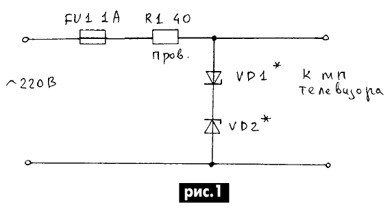
Encyclopedia of radio electronics and electrical engineering / Protection of equipment from emergency operation of the network, uninterruptible power supplies An increase in mains voltage in our time (however, like a decrease) is a common occurrence. The network is literally “teeming” with various impulse noise, and “spikes” of the mains voltage exceed 300 V or more. In rural areas, the situation is even worse. Emergencies lead to the fact that the consumer may have 220 V or more instead of the required 350 V! Mains voltage in the range of 180 ... 260 V is the rule rather than the exception. The most sensitive in this situation are radio-electronic devices (RES). Therefore, it is necessary to protect the RES from possible increases in mains voltage. One of the assembled structures has been successfully operated for more than a year together with the 3USCT TV. Its circuit is extremely simple (Fig. 1), but it is quite effective in protecting the TV from surges in the mains voltage and a sharp increase in mains voltage for a long time.
The power consumed by the TV is approximately 70 W, the range of normal operation of the TV (MP3 power module) with some margin is 180...240 V (175...245). When the voltage increases above 250 V, there is a real threat of failure of the MP TV. The first candidate for failure may be the electrolytic capacitor of the MP rectifier filter (C16, C19). As long as the mains voltage does not exceed 250 V, the circuit has almost no effect on the operation of the TV, with the exception of the voltage drop across the wirewound resistor R1 (about 12,7 V with a power consumption of 70 W and a mains voltage of 220 V). The power dissipated in this mode on the resistor does not exceed 4 W. A two-way mains voltage limiter is assembled on the zener diodes VD1 and VD2. As soon as the mains voltage exceeds 250 V, the zener diodes VD1 and VD2 open and fuse FU1 blows, the TV (its MP) will be de-energized. In addition, the circuit in Fig. 1 effectively suppresses various surges in the mains voltage, limiting them to a safe level. The influence of resistor R1 on the demagnetizing circuits in the TV is small, and its presence in the circuit does not negatively affect the purity of color. In this case, the MP turns on more softly, because current surges occur due to the presence of electrolytic capacitors in the MP rectifier filter. Current limitation by a standard resistor (3,3...4,7 Ohms) occurs at the level of very high currents, which reduces the life of MP diodes and capacitors. Construction and details. As a powerful wire resistor R1, I used a piece of high-resistance wire from the electric stove spiral. Later he made several more similar resistors by parallel connection of MLT-2 resistors with a resistance of 390 ... 680 Ohms. The situation with zener diodes is much more complicated. They must have a high stabilization voltage and (which is very important) a large permissible stabilization current overload for the duration of the blown fuse FU1. Since it was not possible to purchase anything suitable at a reasonable price, I decided to use a “battery” of series-connected domestic zener diodes of the D1A type as zener diodes VD2 and VD815 (stabilization voltage 5...6,2 V, rated stabilization current 1 A, current overload at for 1 s is equal to 2,8 A). The last of the given parameters is quite suitable for the circuit in Fig. 1, since the fuse burns out much faster than 1 s. As VD1 and VD2, I initially installed 50 pcs. D815A. In this case, the clamping voltage (for each half-wave) is: Ulim \uXNUMXd NUst + NUpr, where N is the number of zener diodes connected in series to one branch of the double-sided limiter; Upr - voltage drop across the zener diode in the diode connection (for D815A less than 1,5 V); Ust - stabilization voltage (for D815A less than 6,2 V). In order not to waste time selecting specimens with maximum Ust, I measured the stabilization voltage of the already connected zener diode battery. If it turned out to be insufficient, then he added several zener diodes, and, conversely, if necessary, he removed the extra ones from the circuit. This does not take much time if you use an LATR and an additional transformer to be able to receive a mains voltage of 250 V and higher [1]. During installation, the fuse is temporarily replaced with a 100 W incandescent lamp. When the voltage increases above 250 V, the zener diodes open and limit the voltage, the excess is extinguished by the incandescent lamp (resistor R1 is short-circuited at this time). An ammeter is connected in series with the lamp, thus making it possible to monitor the performance of the circuit. The filament resistance of a light bulb in a cold state is about 40 ohms, so the zener diodes are protected from “shock” currents and emergency situations during setup of the circuit. If the mains voltage is constantly overestimated or often rises to 240 V or more, then you can protect the TV by including one or two resistors in the network wires of the TV (Fig. 2).
To prevent resistors from affecting the demagnetization circuit, they can be turned on directly in front of the MP TV, bypassing the elements of the demagnetization circuit (ST 15-2-220 V; L1, R3-MP-3-3). Resistor values are calculated using the formula R = Udrop/Ipot for one resistor (R = R1 + R2), where Udrop is the part of the mains voltage that needs to be “extinguished”; Ipotr - the current consumed by the TV from the network. The disadvantage of this method is that the operating voltage range of the MP is moved upward, i.e. instead of 170-240 V, it will become 190-260 V, and high-voltage interference and surges are not extinguished. Advantage: simplicity and soft inclusion of MP in the network. Despite the large number of zener diodes, the circuit of Fig. 1 can be assembled very quickly. Heat sinks for the zener diodes were not required, they did not even have time to warm up, as the fuse burned out. The allowable power dissipation for such a "battery" of zener diodes is 800 W! To reduce the number of zener diodes used, the protective device is assembled according to the scheme of Fig. 3. In it, the number of zener diodes is reduced by almost half or more, since the zener diodes are included at the output of the bridge diode rectifier, and some voltage also drops on these diodes. As diodes VD1 ... VD4, you can use any powerful ones with Uobr \u400d 5 V and a permissible current of more than 1 A. With a small power consumption, an incandescent lamp can be used instead of a fuse and resistor RXNUMX.
To visually monitor the operation of the network limiter, an AL307 LED is connected in parallel to one of the zener diodes through a 1 kOhm quenching resistor. Despite the circuit simplicity, these protective devices are very efficient and reliable in operation, are not capricious of "false" trips, and do not themselves cause interference on the network. To protect the circuits of electronic devices from overloads, devices called transient voltage suppressors are produced abroad (for an article about them, see “Radioamator” 2/99 p. 31). By now, Russian analogues have also appeared, called limiting zener diodes. They have a power dissipation of up to 10 kW, which is enough to blow a fuse. There is also a class of devices such as supervisors or overvoltage or undervoltage detectors. For example, the KR1171SP16 microcircuit has an operating voltage of 16 V. At this voltage, the output switch of the microcircuit opens, through which you can turn on a self-locking relay. You can turn it on at the input through a voltage divider. Since it is still difficult for a radio amateur to obtain such elements, you can also use the devices described in the article. References:
Author: A.G. Zyzyuk
Machine for thinning flowers in gardens
02.05.2024 Advanced Infrared Microscope
02.05.2024 Air trap for insects
01.05.2024
▪ space mission to save the planet ▪ Gaming platform for virtual games Virtuix Omni ▪ Drugs will be tested on a human simulator
▪ section of the site Electrical safety, fire safety. Article selection ▪ Nozdrev article. Nozdrevshchina. Popular expression ▪ Which animal males can pretend to be females? Detailed answer ▪ article Make an air barometer. Children's Science Lab ▪ See Parallel Phone Call. Encyclopedia of radio electronics and electrical engineering
Home page | Library | Articles | Website map | Site Reviews
www.diagram.com.ua |


 Leave your comment on this article: