|
|


 Arabic
 Bengali
 Chinese
 English
 French
 German
 Hebrew
 Hindi
Hindi Italian
 Japanese
 Korean
 Malay
Malay Polish
 Portuguese
 Spanish
 Turkish
 Ukrainian
 Vietnamese
|
ENCYCLOPEDIA OF RADIO ELECTRONICS AND ELECTRICAL ENGINEERING Switching voltage regulator, 8-60/5 volts 2 amps. Encyclopedia of radio electronics and electrical engineering
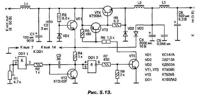
Encyclopedia of radio electronics and electrical engineering / Surge Protectors This stabilizer differs from similar ones in circuit simplicity and high values of stabilization and efficiency coefficients. It uses the widespread K155LAZ chip (or its equivalent). This stabilizer was used to power a digital device, and in the manufacture of various digital devices there will always be a couple of extra inverters. The stabilizer (Fig. 5.13) consists of the following functional units: launch unit (R3, VD1, VT1, VD3), exemplary voltage source and comparison device (DD1.1, R1), DC amplifier (VT2, DD1.2, VT5 ), a transistor switch (VT3, VT4), an inductive energy storage device with a switching diode (VD2, L2) and filters - input (L1, C1, C2) and output (C4, C5, L3, C6).
Main technical characteristics:
The printed circuit board of the stabilizer is shown in fig. 5.14.
After the power is turned on, the start-up unit comes into operation, which is a parametric voltage stabilizer with an emitter follower. A voltage of about 1 V appears at the emitter of the transistor VT4. Since there is no voltage at the output of the stabilizer yet, the VD3 diode is closed. As a result, the exemplary voltage source and the DC amplifier are turned on. The transistor key is still closed. Since the supply voltage of the DD1.1 element is less than 5 V, a high logic level is set at its output, a steep front of the switching pulse is formed at the output of the DC amplifier. This front quickly (within about 30 ns) opens the electronic switch, which starts to pass current into the inductive energy storage. The current through the switch and the voltage across the capacitor C4 will increase smoothly. As soon as this voltage exceeds the voltage at the zener diode VD1, the diode VD3 will open, and the transistor VT1 will close. The launch node will be turned off, and it will not take part in further work. From this moment, the negative feedback circuit is switched on in the stabilizer, and it goes into working condition. The voltage on the capacitor C4 continues to increase until the level 1.1 changes to 1 at the output of the DD0 element. The DC amplifier generates a drop in the switching pulse, which does not close the electronic key for about 200. Up to this point, electromagnetic energy has accumulated in the inductor L2. Part of the energy that has passed through the electronic key is fed into the load. Further, the self-induction voltage of the inductor L2 opens the VD2 diode, and the energy accumulated in this inductor begins to flow into the load. In order to reduce the amplitude of the voltage surge that is dangerous for the DD1 microcircuit, the capacitance of the capacitor C4 is chosen to be very large, while usually it does not exceed several tens or hundreds of microfarads. After the energy reserve in the inductor L2 is exhausted, the current will flow into the load from the capacitor C4. After some time, the voltage on it will decrease to a value when the front of the next switching pulse is formed at the output of the DC amplifier and the electronic key opens again - a new cycle of the stabilizer will begin. All inductors are the same and are wound in B20 armored magnetic circuits made of 2000NM ferrite with a gap between the cups of about 0,2 mm. The windings contain 20 turns of a bundle of four PEV-2-0,41 wires. You can also use ring ferrite magnetic circuits, but always with a gap. If a neat gap could not be obtained and the ring split into several parts, then the necessary gap (about 0,2 mm) can be created in this case as well. To do this, several layers of glue are applied to the surfaces to be glued, for example, "Supercement", until completely dry, and then the fragments are glued into a ring. The number of turns and the wire are not critical in this case either. The stabilizer used capacitors K52-2 or others, but always tantalum or niobium (when replacing with K50-6, efficiency decreases); K50-6 (C4 and C6), the rest - KM-5 or. KM-6. Capacitor C2 is made up of three 1 uF capacitors connected in parallel. Diode VD3 can be replaced by any pulsed low-power diode. Instead of the KT3102G transistor, KT3102E, KT342V, KT373V are suitable; instead of KT608B (VT1) - KT503D, KT503E, and at the output of the DC amplifier - KT608B, KT602B, KT630A.KT630G. In the key element, transistors KT908B, 2T908A, 2T912B, KT912B can be used, and with a slight deterioration in efficiency - KT808A. It is impossible to use transistors of the KT909 series, as this will lead to excitation of the key at a high frequency and failure of the entire device. The transistors of the KT802, KT803, KT805, KT819, KT827, KT829 and KT818, KT825 series were also tested, but showed the worst results (in the last two cases, the key circuit was changed accordingly). All parts used must be carefully checked. Before mounting the tuning resistor R1 on the board, its resistance is set to 3,3 kOhm. The stabilizer is first turned on at a supply voltage of 8 V and a load resistance of 10 ohms, after which the output voltage is controlled and, if necessary, set by resistor R1 to a level of 5 V. The voltage is finally set after the stabilizer has warmed up for 10 ... 16 minutes. If the VD2 diode and the VT4 transistor are installed on heat sinks, the stabilizer can provide a load current of up to 4 A, but in this case it is better to make up the VD2 diode in the switch from several 2D213A diodes connected in parallel. It should be noted that in some modes of operation of the stabilizer, the transients on the collector of the VT4 transistor and on the basis of the VT3 transistor can differ significantly. The voltage at the emitter of the transistor VT4 may contain parasitic oscillations due to wave processes in a complex output filter, which, however, do not worsen the overall efficiency. Author: Semyan A.P.
Artificial leather for touch emulation
15.04.2024 Petgugu Global cat litter
15.04.2024 The attractiveness of caring men
14.04.2024
▪ Intel: a breakthrough in photonics ▪ Brain chip to restore vision ▪ A new planet has been discovered in the solar system
▪ section of the site Calls and audio simulators. Article selection ▪ Article Emergencies. Classification of emergency situations. Basics of safe life ▪ article When did a man start shaving his beard? Detailed answer ▪ Article Botulism. Health care ▪ Article Artificial oil. Simple recipes and tips
Home page | Library | Articles | Website map | Site Reviews
www.diagram.com.ua |


 Leave your comment on this article: