|
|


 Arabic
 Bengali
 Chinese
 English
 French
 German
 Hebrew
 Hindi
Hindi Italian
 Japanese
 Korean
 Malay
Malay Polish
 Portuguese
 Spanish
 Turkish
 Ukrainian
 Vietnamese
|
ENCYCLOPEDIA OF RADIO ELECTRONICS AND ELECTRICAL ENGINEERING Power supply / charger 20 volts 5 amps. Encyclopedia of radio electronics and electrical engineering
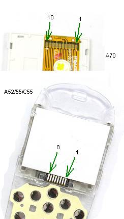
Encyclopedia of radio electronics and electrical engineering / Power Supplies I’ll make a reservation right away that it is possible to make a power supply unit for a different maximum output voltage and current, later it will be described why and how to do this (the 20 volt 5 amp option is considered in the circuit). In this design, one of the following displays from Siemens cell phones can be used: A70, A52, A55, C55, possibly from some others that are not known to me. The pinout for these displays is shown in the figure.
So, to set up and configure the PSU, we need 1. Tester (voltmeter, ammeter) and it is desirable that it measures accurately enough.
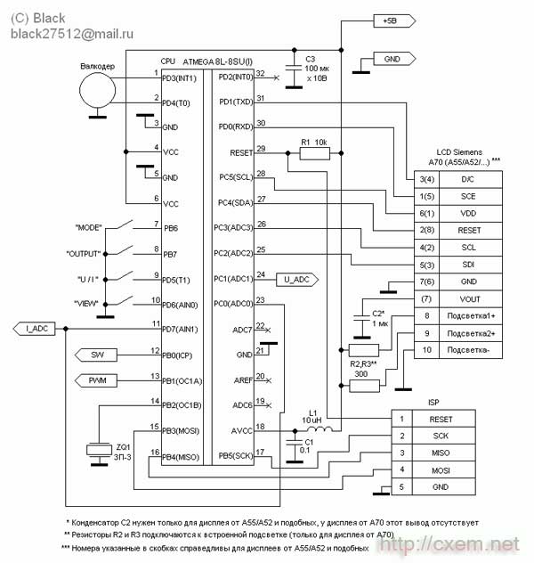
Now a little on the design All control in the circuit is carried out by the ATmega8 microcontroller, it is clocked from the internal RC circuit, which is indicated by the absence of quartz :) It measures the output voltage and current with its internal ADC, and controls the output voltage with an internal PWM modulator. Current protection (short circuit protection) is implemented through the internal comparator. Through the ports, the controller controls the relay, polls the buttons and the encoder, and displays the image on the display. The valcoder can be applied to any design (for example, I removed it from the front panel of a Sony car radio :)). You can make it from an old computer mouse (ball mouse, although I came across infa about how to make it from an optical mouse as well). The VT2 transistor is installed on a radiator with an area based on the maximum power that you need. For example, with a transformer voltage of 24V and load power at 10V 1A, we get: P \u24d (Utransformer - Uload) x I load; (10V-1V) x 14A = XNUMX Watts!
Programming There are two firmwares, they are the same, but they are designed for different displays (for A70 and for all others). You can flash the controller both in-circuit and separately on the programmer. Do not forget to flash the EEPROM area (if it is not flashed, the PSU will not work correctly). I recommend flashing the controller separately from the circuit, because. this device is powered by the network and during the firmware process, the controller / programmer / PC port itself may fail. However, if a controller is used in a planar package, then it is more convenient to flash it in-circuit. But here it is imperative to observe safety measures, namely: there must be a very reliable ground (common bus) between the programmer, PC and the device, connect / disconnect the programmer from the device only with the plug (the PSU itself) removed from the socket, do not trust the network filter switches ! They often stand on only one of the network wires! And so we figured out the firmware, after flashing the code, you still need to set the configuration bits. Be careful with them, especially with CKSEL, RSTDSBL, SPIEN! If they are installed incorrectly, the controller may no longer be seen by the programmer! Set the bits in the following order: ;BootLock12 = Programmed(1)
Now about setting up the device After turning on (mains voltage is applied), you need to check the voltage at the output of the diode bridge (in my case it should be 24V) and the voltage at the 3rd pin of DA2, in any case it should be 5V.
This is the 4th parameter in a row, when you press U / I, you will go to parameter number 1 (one long beep will be heard), when you press it again, you will go to the 2nd (two beeps) and so on up to 4 and in a circle , parameter changes are immediately applied to the display (monitored visually). The change of the parameter is made by the knob of the encoder, the change is accompanied by short beeps. To save the configured parameters and switch to the operating mode, press OUT. Next, you need to configure the analog part of the circuit: To do this, also turn off the power supply, hold down the MODE and VIEW buttons, and turn on the power. You will see the following on the display:
The threshold indicates the state of protection against short circuit, 0 - the current is normal, 1 - the current is exceeded, U-DAC - the state of the PWM modulator (the value of the set voltage), I-ADC - the current measured current, U-ADC - the current measured voltage. All buttons work: OUT / MODE - control the output relay, VIEW / U / I - control the buzzer (for testing). The setup procedure is as follows: press OUT (turn on the relay), set the U-DAC value to 500 with the encoder, connect a voltmeter to the PSU output and set half of the maximum output voltage with resistor R4 (in my case it is 10 volts). Next, with the resistor R9, achieve the same readings of the U-ADC and U-DAC (that is, so that the U-ADC also has 500). Everything, the voltage is set, the current remains. Set the U-DAC to zero, connect an ammeter and a dummy load (resistor) to the output in series. Raise the value of the U-DAC by controlling the current in the load, set some round value (for example, 500 mA, 1A, etc.), use the resistor R7 to achieve the required value in the I-ADC (that is, 500 is the maximum current, in my case 500mA is 50, 1A is 100). That's all, the setup of the analog part is completed. Next, we configure the program for the real values of voltage and current. To do this, turn off the PSU, hold down the VIEW and U / I buttons and turn on the power. On the display we see the following:
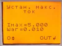
With a rotary encoder, we set our maximum voltage (by the way, it should be a multiple of 5 volts). Press OUT.
We set our maximum current with the encoder. Press OUT.
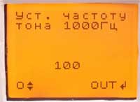
And that's where the frequency counter is needed. We connect the frequency meter in parallel with ZQ1 and set the encoder to 1 kHz. Press OUT. This completes the setup, and the PSU switches to the operating mode. Now a little about how to use the PSU and the modes of operation In voltage source mode, 3 parameters can be changed. These are the output voltage, limiting/protection current and protection operation mode.
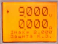
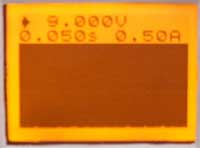
All parameters are controlled by a rotary encoder, switching between parameters is done with the U / I button, there are 4 protection modes: Limitation - current is limited to Imax, Imax protection - protection is triggered when Imax is exceeded, Short circuit protection. - protection works only when the maximum allowable current is exceeded (Imax does not play a role), No protection! - protection is disabled at all, but be careful with this mode, in case of a short circuit, the circuit may fail! This mode is implemented for those cases when a device is being tested with the presence of peak excess current consumption (for example, ULF, subwoofer, etc.). Yes, the OUT button controls the voltage output to the terminals, you can judge the state of the output voltage by the readings of the ammeter (if there are dashes, then the output is disabled, if the value is in numbers, then the voltage is applied to the terminals). When the protection is triggered, a short beep is heard, to reapply voltage to the terminals, press OUT. When you click on VIEW, the PSU switches to the mode of graphical display of the current consumption in the form of an oscillogram. In this case, the selected protection mode and voltage is saved.
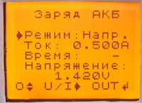
In this mode, you can control the output voltage and the "time / division" parameter, the value in seconds indicates the sweep time of the entire width of the display. To the right of the "time/div" parameter is the "ampere/div" parameter, it cannot be adjusted, it is set automatically from the minimum to the maximum, depending on the current maximum consumption current. This value shows the entire height of the graph vertically, that is, the top of the graph is the value that is indicated in amperes. To reset it to the minimum, you need to press VIEW twice, that is, go to normal mode and go back. The PSU also has a charger that charges the batteries with direct current. To switch to the battery charge mode, you need to press the MODE button, but for this the output voltage must be turned off, otherwise the transition is blocked (done as a protection against accidental pressing during operation).
And so the charger, there are 2 modes: Voltage mode - charges up to the specified voltage with the maximum specified current, when the specified voltage is reached and the charge current drops by 4 times, the charge is completed, Time mode - everything is exactly the same, but no attention is paid to the charge current, and the charge stops after the specified time. The time is set in minutes. The start is carried out by the OUT button, when the charge is completed, the device emits a long beep and displays a message on the display about the end of the charge. You can interrupt the charging process at any time by pressing any button. That's all. I think I've given enough detail. Questions can be sent to e-mail: black27512@mail.ru or ICQ: 330898528. P.S. It may seem to you that something is missing in the device or something is not done properly (for example, it is advisable to use a more multi-bit ADC and DAC, etc.). But understand, I sought to make the device as cheap and simple as possible in the first place. But in any case, I look forward to comments and suggestions, where without them. And I used a graphic display in order to be able to display an "oscillogram", this is often useful when repairing such complex devices as, for example, cell phones ... Download firmware and board in LAY format Author: Alexey Chernov; Publication: cxem.net
Machine for thinning flowers in gardens
02.05.2024 Advanced Infrared Microscope
02.05.2024 Air trap for insects
01.05.2024
▪ The threat to the ancient city of the Incas ▪ Modeling the Structure of Solid State Batteries ▪ New ATtiny 24/44/84 processors
▪ section of the site Dosimeters. Selection of articles ▪ article by Richard Brautigan. Famous aphorisms ▪ Zharka's article. Legends, cultivation, methods of application
Home page | Library | Articles | Website map | Site Reviews
www.diagram.com.ua |


 Leave your comment on this article: