|
|


 Arabic
 Bengali
 Chinese
 English
 French
 German
 Hebrew
 Hindi
Hindi Italian
 Japanese
 Korean
 Malay
Malay Polish
 Portuguese
 Spanish
 Turkish
 Ukrainian
 Vietnamese
|
ENCYCLOPEDIA OF RADIO ELECTRONICS AND ELECTRICAL ENGINEERING Harmonic crystal oscillators
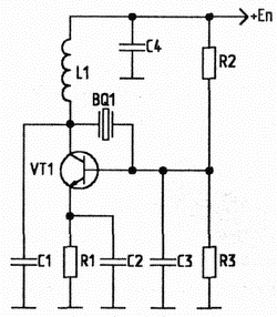
Encyclopedia of radio electronics and electrical engineering / Knots of amateur radio equipment. Generators, heterodynes Modern transceivers require increased accuracy of tuning to the operating frequency. This requirement is quite easy to ensure by applying quartz frequency stabilization. Typically, quartz resonators in generators are excited at the fundamental frequency (up to 20 ... 22 MHz). This is due to the fact that quartz resonators, as a rule, have an AT cut, that is, they use shear oscillations (through the thickness of the quartz plate). Since at a frequency of 22 MHz the thickness of the quartz plate is less than 0,08 mm, it is technologically difficult to obtain thinner plates without significantly increasing the cost of the resonator. Usually, above the specified frequency, the resonators excite at odd mechanical harmonics. For this purpose, an inductor (Fig. 1) is included in a quartz oscillator, made according to the capacitive three-point scheme. The resulting parallel oscillatory circuit, formed by the coil L1 and capacitor C1, is tuned to a frequency below the working harmonic, but above the previous one. Then, at the frequency of the required harmonic, the resistance of the circuit has a capacitive character, and at a lower one, it is inductive. As a result, the balance of phases and amplitudes is performed only on the working harmonic.
In principle, it is possible to excite quartz resonators at the third harmonic without using an inductor, as shown in Fig. 2. The excitation of the resonator at the harmonic is described in [1]. In this circuit, the quartz is connected between two gates of a high-frequency field-effect transistor with a choke (L1) load in the drain circuit. This provides the necessary phase shift to excite quartz at the third harmonic. The generator load is connected through a source (emitter) follower. Otherwise, the load capacitance in most cases leads to a breakdown of oscillations (for the third harmonic). This oscillator circuit has good performance. It excites both obsolete RK-169 type quartz and modern ones (German company "Jauch", St. Petersburg production company "Morion").
The circuit was tested with quartz resonators at frequencies from 5 to 16 MHz. When using resonators from 5 to 9 MHz, it was necessary to increase the inductance of the inductor to 100 μH. By adjusting the voltage at the second gate using R1, it is possible to achieve the excitation of quartz at the third harmonic and the required oscillation amplitude at the output of the circuit. Instead of a double-gate field-effect transistor of the BF961 type, you can try to use KP327, KP359, but not all types of quartz resonators will be excited at the third harmonic. In the following scheme, shown in Fig. 3, quartz resonators are also excited at the third harmonic.
A reader experienced in radio engineering, having carefully looked at the circuit, may doubt the operability of the proposed generator, because. a relatively large resistance (R2) is included in the collector circuit, and only 100 ohms (R1) between the base and the collector. In this case, the transistor VT1 is used in diode switching, when the base and collector have the same potential relative to the common wire of the circuit. The current through the transistor is set by a resistor in the collector circuit. And the resistor R1 is necessary only in order to extinguish parasitic oscillations in the circuit formed by the inductor L1 and the capacitance of the base-collector junction of the transistor, together with the parasitic capacitances of the circuit. In view of the fact that the h-parameters of the transistor depend on the mode of its operation and on the frequency, the proposed circuit balances the phases and amplitudes at the third harmonic of the quartz. The load of the crystal oscillator is connected through a source (emitter) follower with a high input impedance. In this scheme, both evacuated (RK100, RK-259) and sealed (RK-169) quartz resonators are excited. The circuit was tested with quartz at frequencies from 5 to 16 MHz. With some types of low-frequency quartz, for more reliable excitation of oscillations, it is necessary to increase R1 to 220 ohms, capacitance C2 to 36 pF. When using "low-active" quartz, it is desirable to increase the inductance of the inductor L1 to 50 μH. Even with unfavorable ratios of the elements of this quartz oscillator, when the power was changed from 4 to 12 V, it was possible to excite quartz at the third harmonic. Transistors in the generator can be used types KT315, KT306, KT325, KT355, KT399, you only need to select L1, C2 and change the supply voltage to work with the required type of quartz resonator. The next scheme offered to the attention of readers (Fig. 4) is somewhat more complicated, but there are no winding products in it. In this circuit, the phase balance is performed when the quartz is excited at the third harmonic using an RC circuit.
The oscillator is made on a differential stage. The left (according to the circuit) transistor of the differential stage is connected according to the circuit with a common base, the right one - according to the circuit with a common emitter. A phase-shifting RC circuit R5-C3 is connected between the collectors of the transistors. The circuit under consideration belongs to oscillatory ones, since without a quartz resonator, which is an equivalent inductance, oscillations do not occur. In the circuit, resonators are well excited at frequencies from 5 to 16 MHz. For low-frequency quartz, it is necessary to increase the capacitance C3 to 10 pF. When changing the elements of the phase-shifting circuit: resistor R5 - from 10 to 150 Ohm, capacitance C3 - from 0 to 10 pF, it was possible to obtain stable oscillations at the third mechanical harmonic of quartz. The DA1 transistor assembly can be replaced with a matched pair of high-frequency transistors KT306, KT368, KT325, KT355, KT399. In this circuit, the load also needs to be connected through a cascade with a high input impedance. The nominal supply voltage is 9 V, but to excite oscillations it is sometimes useful to “pump” it in the range from 4 to 12 V. Literature
Author: O. Belousov, Cherkasy; Publication: radioradar.net
Artificial leather for touch emulation
15.04.2024 Petgugu Global cat litter
15.04.2024 The attractiveness of caring men
14.04.2024
▪ Microrobots for the repair of underground utilities ▪ Prosthetic arm using Formula 1 technology ▪ High Voltage MOSFETs for High Speed Switching Devices ▪ Hyperstable artificial protein
▪ radio section of the website. Article selection ▪ article by William Faulkner. Famous aphorisms ▪ Article Mustard sarepta. Legends, cultivation, methods of application ▪ article Bandwidth Throttling. Encyclopedia of radio electronics and electrical engineering
Home page | Library | Articles | Website map | Site Reviews
www.diagram.com.ua |


 Leave your comment on this article: