|
|
ENCYCLOPEDIA OF RADIO ELECTRONICS AND ELECTRICAL ENGINEERING Pulse metal detector. Encyclopedia of radio electronics and electrical engineering
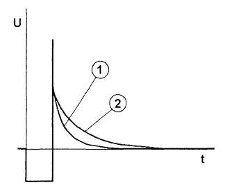
Encyclopedia of radio electronics and electrical engineering / metal detectors The impulse metal detector brought to your attention is a joint development of the author and engineer from Donetsk (Ukraine) Yuri Kolokolov (web address - home.skif.net/~yukol/index.htm), who managed to translate the idea into a finished product based on a programmable single chip microcontroller. He developed the software, as well as carried out full-scale tests and extensive debugging work. At present, the Moscow firm "Master Kit" is planning to produce kits for radio amateurs for self-assembly of the described metal detector. The kit will contain the printed circuit board and electronic components, including the already programmed controller. Perhaps, for many lovers of treasure hunting and relics, the purchase of such a kit and its subsequent simple assembly will turn out to be a convenient alternative to purchasing an expensive industrial device or making a metal detector completely on your own. For those who feel self-confident and are ready to try to make and program a microprocessor pulsed metal detector, on the personal page of Yuri Kolokolov on the Internet there is a trial version of the controller firmware in Intel HEX format and other useful information. This firmware version differs from the full version in the absence of some metal detector operation modes. The principle of operation of a pulse or eddy current metal detector is based on the excitation of pulsed eddy currents in a metal object and the measurement of the secondary electromagnetic field that these currents induce. In this case, the excitation signal is supplied to the transmitting coil of the sensor not constantly, but periodically in the form of pulses. In conducting objects, damped eddy currents are induced, which excite a damped electromagnetic field. This field, in turn, induces a damped current in the sensor's receiving coil. Depending on the conductive properties and the size of the object, the signal changes its shape and duration. On fig. 24. schematically shows the signal on the receiving coil of a pulsed metal detector.
Pulse metal detectors have their advantages and disadvantages. The advantages include low sensitivity to mineralized soil and salt water, the disadvantages are poor selectivity by metal type and relatively high energy consumption. Practical Design Most practical designs of pulsed metal detectors are built either on a two-coil circuit, or on a single-coil circuit with an additional power source. In the first case, the device has separate receiving and emitting coils, which complicates the design of the sensor. In the second case, there is only one coil in the sensor, and an amplifier is used to amplify the useful signal, which is powered by an additional power source. The meaning of this construction is as follows - the self-induction signal has a higher potential than the potential of the power source, which is used to supply current to the transmitting coil. Therefore, to amplify such a signal, the amplifier must have its own power source, the potential of which must be higher than the voltage of the signal being amplified. It also complicates the device circuit. The proposed single-coil design is built according to the original scheme, which is devoid of the above disadvantages. Main Specifications
Depth of detection:
Despite the relative simplicity of the design of the proposed pulse metal detector, its manufacture at home may be difficult due to the need to enter a special program into the microcontroller. This can be done only if you have the appropriate qualifications and software and hardware to work with the microcontroller. Structural scheme The block diagram is shown in fig. 25 The basis of the device is a microcontroller. With its help, time intervals are formed to control all nodes of the device, as well as indication and general control of the device. With the help of a powerful key, energy is pulsed in the sensor coil, and then the current is interrupted, after which a self-induction pulse occurs, which excites an electromagnetic field in the target.
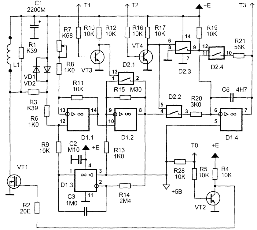
The "highlight" of the proposed scheme is the use of a differential amplifier in the input stage. It serves to amplify the signal, the voltage of which is higher than the supply voltage, and bind it to a certain potential (+5 V). For further amplification, a receiving amplifier with a high gain is used. The first integrator is used to measure the useful signal. During direct integration, the useful signal is accumulated in the form of voltage, and during backward integration, the result is converted into pulse duration. The second integrator has a large integration constant (240 ms) and serves to balance the amplifying path with respect to direct current. Schematic diagram Schematic diagram of a pulse metal detector is shown in fig. 26 - differential amplifier, receiving amplifier, integrators and a powerful switch.
On fig. 27 shows the microcontroller and the controls and indications. The proposed design is developed entirely on the basis of imported components. The most common components from leading manufacturers are used. You can try to replace some elements with domestic ones, this will be discussed below. Most of the elements used are not in short supply and can be purchased in large cities of Russia and the CIS through companies selling electronic components.
A powerful key is assembled on a field-effect transistor VT1. Since the applied field-effect transistor of the IRF740 type has a gate capacitance of more than 1000 pF, a preliminary stage on the VT2 transistor is used to quickly close it. The opening speed of a powerful key is no longer so critical due to the fact that the current in the inductive load increases gradually. Resistors R1, R3 are designed to "quench" the energy of self-induction. Their rating is chosen for reasons of safe operation of the transistor VT1, as well as ensuring the aperiodic nature of the transient process in the circuit, which is formed by the sensor inductance and parasitic interturn capacitance. Protective diodes VD1, VD2 limit the voltage drops at the input of the differential amplifier. The differential amplifier is assembled on the D1.1 op-amp. Chip D1 is a quad operational amplifier type TL074. Its distinguishing features are high speed, low consumption, low noise level, high input impedance, as well as the ability to work at input voltages close to the supply voltage. These properties determined its use in a differential amplifier in particular and in the circuit as a whole. The gain of the differential amplifier is about 7 and is determined by the values of the resistors R3, R6-R9, R11. The receiving amplifier D1.2 is a non-inverting amplifier with a gain of 56. During the action of the high-voltage part of the self-induction pulse, this coefficient is reduced to 1 using the analog switch D2.1. This prevents overloading of the input amplification path and provides a quick entry into the mode for amplifying a weak signal. Transistor VT3, as well as transistor VT4, are designed to match the levels of control signals supplied from the microcontroller to analog switches. With the help of the second integrator D1.3, the input amplifying path is automatically balanced by direct current. The integration constant of 240 ms is chosen large enough so that this feedback does not affect the amplification of the rapidly changing useful signal. With this integrator, the output of amplifier D1.2 is maintained at +5 V in the absence of a signal. The measuring first integrator is made on D1.4. At the time of integration of the useful signal, the key D2.2 is opened and, accordingly, the key D2.4 is closed. A logical inverter is implemented on the D2.3 key. After the integration of the signal is completed, the key D2.2 closes and the key D2.4 opens. The storage capacitor C6 begins to discharge through the resistor R21. The discharge time will be proportional to the voltage that is established on the capacitor C6 by the end of the integration of the useful signal. This time is measured by a microcontroller that performs analog-to-digital conversion. To measure the discharge time of the capacitor C6, an analog comparator and timers are used, which are built into the D3 microcontroller. With the help of LEDs VD3...VD8 light indication is made. Button S1 is intended for the initial reset of the microcontroller. Switches S2 and S3 set the operating modes of the device. Using a variable resistor R29, the sensitivity of the metal detector is adjusted. Functioning algorithm To clarify the principle of operation of the described pulse metal detector in fig. 28 shows waveforms of signals at the most important points of the device.
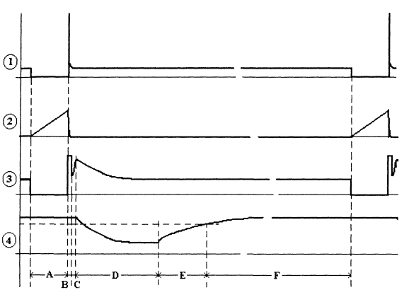
At the time of interval A, the key VT1 opens. A sawtooth current begins to flow through the sensor coil - waveform 2. When the current reaches about 2 A, the key closes. At the drain of the transistor VT1, a self-induction voltage surge occurs - waveform 1. The magnitude of this surge is more than 300 V (!) And is limited by resistors R1, R3. To prevent overloading of the amplifying path, limiting diodes VD1, VD2 are used. Also For this purpose, for the time of interval A (accumulation of energy in the coil) and interval B (ejection of self-induction), key D2.1 is opened. This reduces the end-to-end gain of the path from 400 to 7. Oscillogram 3 shows the signal at the output of the amplifying path (pin 8 D1.2). Starting from interval C, the key D2.1 closes and the gain of the path becomes large. After the completion of the guard interval C, during which the amplifying path enters the mode, the key D2.2 opens and the key D2.4 closes - the integration of the useful signal begins - interval D. After this interval, the key D2.2 closes, and the key D2.4 opens - "reverse" integration begins. During this time (intervals E and F), the capacitor C6 is completely discharged. Using the built-in analog comparator, the microcontroller measures the value of the interval E, which turns out to be proportional to the level of the input useful signal. For firmware version 1.0, the following interval values are set:
The microcontroller processes the received digital data and indicates the degree of impact of the target on the sensor using the VD3-VD8 LEDs and the Y1 sound emitter. The LED indication is an analogue of a pointer indicator - in the absence of a target, the VD8 LED lights up, then, depending on the level of exposure, VD7, VD6, etc. light up sequentially. Part types and design Instead of the operational amplifier D1 TL074N, you can try to use TL084N or two dual op-amps of types TL072N, TL082N. The D2 chip is a quad analog key of the CD4066 type, which can be replaced with a domestic K561KTZ chip. The D4 AT90S2313-10PI microcontroller has no direct analogues. The circuit does not provide circuits for its in-circuit programming, so it is advisable to install the controller on a socket so that it can be reprogrammed. The 78L05 stabilizer can, in extreme cases, be replaced by KR142EN5A. Transistor VT1 type IRF740 can be replaced by IRF840. Transistors VT2-VT4 type 2N5551 can be replaced by KT503 with any letter index. However, you should pay attention to the fact that they have a different pinout. LEDs can be of any type, VD8 is desirable to take a different glow color. Diodes VD1, VD2 type 1N4148. Resistors can be of any type, R1 and R3 must have a power dissipation of 0,5 W, the rest can be 0,125 or 0,25 W. It is desirable to select R9 and R11 so that their resistance differs by no more than 5%. It is desirable to use a tuned resistor R7 multi-turn. Capacitor C1 is electrolytic, for a voltage of 16 V, the rest of the capacitors are ceramic. Capacitor C6 is desirable to take with a good TKE. Button S1, switches S2-S4, variable resistor R29 can be of any type that fits in size. As a sound source, you can use a piezo emitter or headphones from the player. The design of the body of the device can be arbitrary. The rod near the sensor (up to 1 m) and the sensor itself should not have metal parts and fasteners. It is convenient to use a plastic telescopic fishing rod as a starting material for the manufacture of a rod. The sensor contains 27 turns of wire with a diameter of 0,6 ... 0,8 mm, wound on a mandrel 190 mm. The sensor does not have a screen and its fastening to the rod should be carried out without the use of massive screws, bolts, etc. (!) Otherwise, its manufacturing technology can be the same as for an induction metal detector. A shielded cable cannot be used to connect the sensor and the electronic unit due to its high capacitance. For these purposes, it is necessary to use two insulated wires, for example, of the MGSHV type, twisted together. Setting up the device Attention! The device has a high, potentially life-threatening voltage - on the VT1 collector and on the sensor. Therefore, when setting up and operating, electrical safety measures must be observed. It is recommended to set up the device in the following sequence: 1. Make sure the installation is correct. 2. Apply power and make sure that the current drawn does not exceed 100 (mA). 3. Using the trimmer resistor R7, achieve such a balancing of the amplifying path so that the waveform at pin 7 D1.4 corresponds to waveform 4 in fig. 28. In this case, it is necessary to ensure that the signal at the end of the interval D is unchanged, i.e. the waveform at this location should be horizontal. A properly assembled device does not need further configuration. It is necessary to bring the sensor to a metal object and make sure that the indicating elements work. A description of the operation of the controls is given in the description of the software. Software At the time of this writing, software versions 1.0 and 1.1 have been developed and tested. The "firmware" code of version 1.0 in Intel HEX format can be found on the Internet at Yuri Kolokolov's personal page, home.skif.net/~yukol/index.htm. Commercial version 1.1 of the software is planned for delivery in the form of already programmed microcontrollers as part of kits produced by Master Kit. Version 1.0 implements the following features:
Software version 1.1 differs in that it allows you to adjust the sensitivity of the device using a variable resistor R29. Work on new versions of the software continues, it is planned to introduce additional modes. To control the new modes, switches S1, S2 are reserved. New versions, after their extensive testing, will be available in "Master Kit" sets. Information about new versions will be published on the Internet on Yuri Kolokolov's personal page, home.skif.net/~yukol/index.htm. Author: Shchedrin A.I.
Artificial leather for touch emulation
15.04.2024 Petgugu Global cat litter
15.04.2024 The attractiveness of caring men
14.04.2024
▪ GeForce GTX 1650 Low Profile Accelerators ▪ The fabric of the future is changing shape and color ▪ Hydrogen from plants - the basis of future energy ▪ Only half of US residents use landlines
▪ section of the site For a beginner radio amateur. Article selection ▪ Philistine article. Popular expression ▪ article Dombay glade. Nature miracle ▪ article A simple square wave generator. Encyclopedia of radio electronics and electrical engineering ▪ article Avar proverbs and sayings. Large selection
Comments on the article: Dmitriy Hello! And why is the AT90S2313-10PI controller chosen. Does it (metal detector) distinguish between ferrous and non-ferrous metals? I have a desire to make a metal detector on the STM32F030F4P6 controller (we have 50 r / pc). Or on a more multi-legged colleague, if there are not enough legs ... I study the principles of operation ... As I understand it, the task of the controller is as follows: 1) Apply voltage to the coil (output T0) 2) Enable the amplifier protection against reverse impulse (T1) 3) Disable coil and wait for the damping of the self-induction pulse 4) Turn off the amplifier protection (pin T1) and turn on the processing of the useful signal (pin T2) 5) Turn on the timer 6) On interruption from the trigger connected to the T3 pin, take the readings from the timer 7) Compare the value with the reference and give corresponding indication. Thanks for the helpful article. A builder by education, I ask you not to kick me for inaccuracies. This will be the 2nd project using controllers and the 4th or 5th overall from electronics.
Home page | Library | Articles | Website map | Site Reviews www.diagram.com.ua |


 Arabic
 Bengali
 Chinese
 English
 French
 German
 Hebrew
 Hindi
Hindi Italian
 Japanese
 Korean
 Malay
Malay Polish
 Portuguese
 Spanish
 Turkish
 Ukrainian
 Vietnamese


 Leave your comment on this article: