
|
|
UW3DI transceiver upgrade. Encyclopedia of radio electronics and electrical engineering
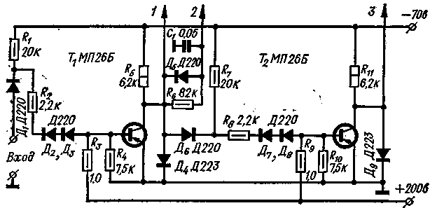
Encyclopedia of radio electronics and electrical engineering / Civil radio communications Many shortwaves successfully work on a transceiver in the telephone sections of amateur bands. But "inveterate" telegraph operators, especially those participating in competitions, cannot be satisfied with the capabilities of this design in the telegraph mode. They need a device that provides half-duplex operation and convenient control of their transmission. Some refinement of the transceiver design ensured that these requirements were met. In addition, the applied contactless switching when switching from reception to transmission and vice versa, it made it possible to get rid of unpleasant clicks of switching relays that tire the operator, and the introduced AGC system - from receiver overloads. In addition, the presence of AGC allows you to objectively assess the loudness of the signal of the received radio station using the S-meter. The non-contact switching is based on the control system (CS), the scheme of which is shown in fig. 1. Together with diode switches, the SU provides fast and reliable switching from reception to transmission and back of all necessary circuits, including antenna switching and receiver detuning relative to the transmitter frequency. The control system has an "Input", to which a telegraph key of any type can be connected, including those with an electronic relay at the output, which, when pressed, gives a level from 0 to -0,5 V and, when released, from -2 to -70 V, a foot switch for telephone control and a voice control system providing the same levels as the electronic telegraph key relay.
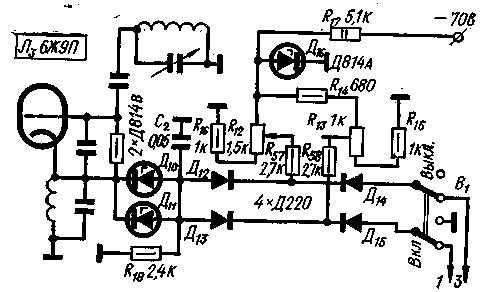
Output 1 is used to supply zero potential to the corresponding diode switches at the time of reception and a level - 50-60 V - at the time of transmission. From output 2, the same potentials are supplied to the control grids of the lamps of the switched cascades of the receiving path. This output has a filter R6, C1 and D5, which eliminates clicks in phones at the moment of transition from transmission to reception. Output 3 is used to supply a level - 50-60 V at the time of reception and zero potential - at the time of transmission to the corresponding diode switches and control grids of the lamps of the switched cascades of the transmission path. When properly installed, the SU does not require any adjustments. Smooth range generator circuit slightly modified (Fig. 2) - the detuning of the receiver is carried out electronically. Zener diodes D10 D11 are used as a varicap. In this case, the detuning is obtained within + 7 kHz. Additional parts of the generator are placed on a mounting plate with dimensions of 60X30 mm, which is located on the chassis wall in the place where the relay P2 previously stood. Instead of the capacitor C25, a variable resistor R12 of the PPP type is installed.
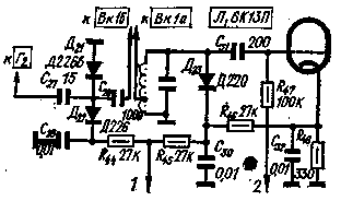
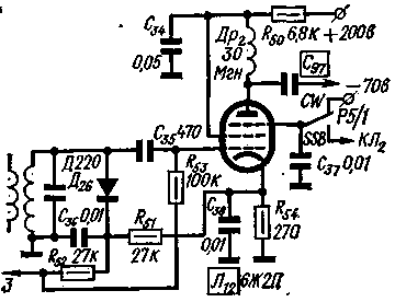
The adjustment of this node is reduced to the selection of the resistance of the resistor R16 so that the constant voltage on it somewhat exceeds the amplitude of the alternating voltage at the cathode of the lamp L3. On fig. 3 shows the circuit manipulated generator to the 500 kHz frequency used to receive the telegraph signal, and changes made to the first transmitter mixer and the second receiver mixer. The use of such a generator makes it easy to obtain the frequency shift necessary in the telegraph mode during reception and transmission, as well as to carry out self-control by passing the signal through the capacitance of the relay contacts P1 / 1 (the relay itself is not shown in the diagram). The generator is assembled on the L1 lamp according to the transitron scheme. A buffer stage is made on the L2 lamp.
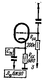
The signal level is adjusted both in CW mode and in SSB mode by simultaneously changing the negative voltage on the third grids of the buffer stage lamps and the DSB amplifier using resistor R26. The telegraph keyed oscillator and the buffer stage are assembled on a separate board and installed in the free space of the transceiver chassis. Relays P1 and P2 - type RES-15, the same as the relays used in other units of the transceiver. Coil L1 is wound on an SB-12a core and contains 80 turns of PEL 0,1 wire. Has undergone a change and IF amplifier (see Fig. 4). It is made on lamps 6ZH2P. The control voltage from the AGC rectifier on diodes D16-D19 or from the manual gain controller RRU on the resistor R27 (shown in the diagram in Fig. 3) is supplied to the third lamp grids. Measuring device IP1 works as an S-meter in the AGC mode and as a milliammeter that controls the anode current of the output stage - in the RRU mode. When working by telegraph, the IF amplifier is turned on during transmission, and when working on SSB during transmission, it is closed.
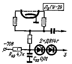
Winding II of the transformer Tr2 contains twice, and winding III - three times less turns than winding 1. On fig. Figures 5-8 respectively show the changes made to the receiver input circuit, the output stage grid circuit, the DSB amplifier, and the transmitter's second mixer. The changes made to the cathode and grid circuits of the other manipulated stages are not shown. Resistors included in the cathode circuits should be connected to a common wire, and grid leakage resistors (in those stages where they were not, they should be installed additionally, together with separating capacitors) - respectively, to output 2 of the control system for the receiving path and output 3 - for the transmitter.
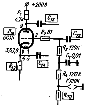
Author: V. Kozlov (UW3BN) Moscow When working in the range of 28-29,7 MHz, especially with novice amateurs, sometimes there are difficulties associated with the lack of a receiver for receiving an SSB signal. Therefore, it was decided to introduce changes into the UW3DI transceiver, allowing you to get an amplitude modulated signal. These changes boiled down to the following. In order to receive AM signal, the normally open contacts of the relay P3 in the receive mode break the cathode circuit of the right (according to the scheme) half of the lamp L6. At atom, the left half of the lamp plays the role of an amplitude detector. With the help of two relays of the RES-15 type, the EMF is shunted by a 5 pF capacitor. The winding of the output transformer of the modulator, which was used as an amplifier UM-700, is included in the break in the power circuit of the final stage (+50 V). To work in the amplitude modulation mode, the switch position P2 "CW Reception" is used (according to the diagram - the second from the right). Authors: I. Romanov (RA0SAI), V. Za-Mullo (RA0SAM) Bratsk A fairly common case when repeating the UW3DI transceiver is insufficient excitation amplitude in transmit mode on the 10m band, resulting in little transceiver output power. One of the reasons for this phenomenon, in my opinion, is that in the transceiver, two cascades on a triode (left half of the L10 lamp) and a pentode (L3 lamp) are simultaneously connected to a band-pass filter (on the 130 m range - L13C2L10). Apparently, a large difference in their internal resistances adversely affects the operation of the transceiver. After the 6Zh9P (L10) pentode was replaced by the 6S3P triode (see Fig. 9), the output power of the transceiver increased sharply by 10 b. In H, the voltage at the cathode of the 6C3P lamp should be 2 V, on the grid - 0,8-1 V. Instead of 6C3P, one half of the 6N23P lamp can also be used.
In the same cascade, telegraph manipulation is carried out (resistor R71 is connected to a common wire). Author: V. Soloshenko (UB5YD) Cherkasy As is known, speech intelligibility practically does not deteriorate if the speech spectrum is limited from below to a frequency of 300 Hz. This limitation allows you to get rid of the AC background, which almost always occurs in network equipment. For example, the cathode-coupled linear detector used in the UW3DI transceiver has an increased background level, the cause of which is the LF voltage from the heater to the ungrounded lamp cathode. Lower limiting the bandwidth of the low-frequency path is usually carried out using LC filters or passive RC high-pass filters.
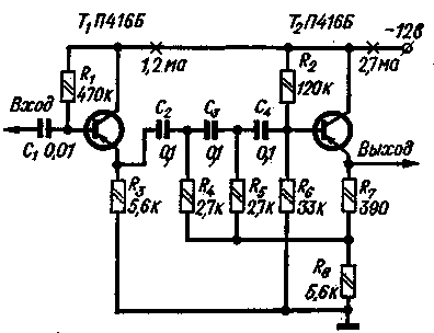
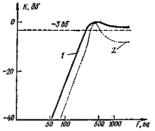
However, passive RC filters are inefficient, and the inductance of the coils of LC filters reaches a value of several henries, which creates certain difficulties in the design of equipment. Good results are obtained when active RC high-pass filters are used for this purpose. A schematic diagram of such a filter with a cutoff frequency of about 270 Hz is shown in fig. 10. The cutoff frequency of the filter is determined mainly by the capacitance of the capacitors C2-C4 and the resistance of the resistors R4-R6. So, if we take R4=R5=5,6 kohm and R6=120 kohm, then with the capacitance of the filter capacitors unchanged, the cutoff frequency will drop to 150 Hz. The resistance of the resistor R7 affects the unevenness of the amplitude-frequency characteristic (AFC) in the passband and the filter gain. On fig. Figure 11 shows the normalized frequency response of the filter (curve 1), and the gain corresponding to the maximum frequency response is taken as 0 dB. The absolute value of the transmission coefficient is usually in the range of 0,5-2,0. The steepness of the slope of the frequency response outside the passband, as can be seen from fig. 11 reaches 15dB per octave, and the 50Hz signal rejection exceeds 40dB with passband ripple less than 3dB.
Curve 2 in the same figure illustrates the effect of the resistance of the resistor L on the frequency response; and corresponds to the case when R7=0. The input impedance of the filter is low, so an emitter follower must be used to use it with lamp devices. Such a follower, providing an input resistance of about 250 kΩ, is assembled on a transistor T1. Both in the filter and in the emitter follower, you can use any low-power transistors with Vct not less than 70-80. Author: B. Stepanov (UW3AX), Moscow; Publication: N. Bolshakov, rf.atnn.ru
The world's tallest astronomical observatory opened
04.05.2024 Controlling objects using air currents
04.05.2024 Purebred dogs get sick no more often than purebred dogs
03.05.2024
▪ Home CHP ▪ The updated line of Wireless Plus from Seagate ▪ New opportunities for overclocking 7nm chips ▪ Magnetic gearbox without gears
▪ section of the site Sites of amateur radio equipment. Article selection ▪ article Thus Spoke Zarathustra. Popular expression ▪ article What French word, being in Russian, was borrowed back by the French? Detailed answer ▪ article Inspector of the pass office. Job description ▪ article Battery discharge indicator. Encyclopedia of radio electronics and electrical engineering
Home page | Library | Articles | Website map | Site Reviews www.diagram.com.ua |


 Arabic
 Bengali
 Chinese
 English
 French
 German
 Hebrew
 Hindi
Hindi Italian
 Japanese
 Korean
 Malay
Malay Polish
 Portuguese
 Spanish
 Turkish
 Ukrainian
 Vietnamese

 Leave your comment on this article: