|
|


 Arabic
 Bengali
 Chinese
 English
 French
 German
 Hebrew
 Hindi
Hindi Italian
 Japanese
 Korean
 Malay
Malay Polish
 Portuguese
 Spanish
 Turkish
 Ukrainian
 Vietnamese
|
ENCYCLOPEDIA OF RADIO ELECTRONICS AND ELECTRICAL ENGINEERING Installation for exposure of photoresist at home. Encyclopedia of radio electronics and electrical engineering
Encyclopedia of radio electronics and electrical engineering / Ham Radio Technologies The times of manual drawing of printed circuit boards are a thing of the past and at the moment radio amateurs are divided into two camps - adherents of laser ironing technology (hereinafter referred to as LUT) and photoresistive. The author started with LUT technology, but under the influence of photoresist adherents, he decided to master this method, and this article is a generalized result of creating a simple setup for making boards by photomethod. There is a lot of information on the Internet about what a photoresist is and how to use it, and we will not delve into this in this material. For us, it is enough to know one thing - to expose the photoresist, you must have a source of UV radiation with a wavelength of 330-470 nm. Since it can take a very long time to wait for a clear sunny day in mid-latitudes, let's see what we have from improvised sources of UV radiation. 1. Burners from lamps DRL-125 and above, which hang on poles along the roads.
Burners from DRL lamps, like DRSh and DRT lamps, require a powerful choke. And very bulky and heavy. DRSH lamps also require a spark generator for ignition, which also cannot inspire optimism. DRB lamps are started with standard chokes from fluorescent lamps of the same power and in the same fittings, but the large linear dimensions of the tubes make their use in an amateur radio workshop problematic. First, the author assembled a photoprojection installation on a DRSH-250 lamp. Its major disadvantage was the pinpointness of the light source, which, without the use of appropriate diffusing quartz optics, makes it unsuitable for obtaining uniform illumination of large boards. Optics could not be obtained: Therefore, the next option was on a DRT-250 lamp (tubular). With it, the uniformity of illumination became acceptable (especially when using 2 pieces in parallel, but a number of big inconveniences in use were revealed. It: 1. Long warm-up time (at least 15 minutes) to stabilize the lamp mode and obtain a uniform UV flux, without which it is almost impossible to obtain stable exposure results.
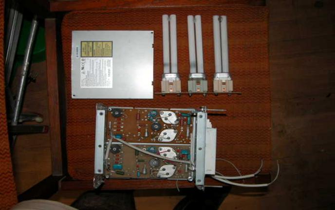
Chance helped to make a workable design. Next to the work, a neighboring bank threw out old currency detectors that use a KL-9 / UV lamp, that is, a compact, luminescent 9 watt ultraviolet. Of course, as a radio amateur, I could not pass by a container with such valuable things. On the basis of three disassembled detectors and an old PSU from a computer server in the AT format, the following design was made:
To do this, electronic ballast boards were installed in the power supply unit with the insides thrown out to the bottom. Since the author managed to save only two boards, a typical 9-watt electromagnetic choke was used for the third lamp. Since these lamps are already equipped with a starter built into the base and a capacity for heating the cathodes, they are switched on in a two-wire circuit. Due to the relatively low power of these lamps and their low heating during operation, a minimum distance of 60 mm was made between the lamp installation plane and the exposure table. The exposure table itself (aka the protective cover over the control gear boards) is made from the tin cover of an old CD-ROM. .It fits perfectly in width to the format of the AT block, only with scissors for metal it must be shortened in length. It is fixed on metal racks of obviously greater length than the parts on the control gear boards. The openings in the power supply case are sealed with commercially available self-adhesive aluminum tape used for ventilation systems. It prevents ultraviolet radiation from escaping to the outside and, by scattering and re-reflecting UV radiation inside the compartment, improves the uniformity of illumination of the template during exposure. The electrical circuit includes three ballasts connected in parallel with lamps connected according to a typical circuit. To ensure the time delay, the author used a time relay on a DIN rail with the ability to set the shutter speed from 30 to 300 seconds. In this design, the exposure turned out to be equal to 250 seconds. In parallel with the relay, a toggle switch of the MT type is installed for the possibility of preheating the lamps. After warming up for 1-2 minutes, the toggle switch opens and the shutter speed set on the time relay is worked out.
Three lamps are installed in a row horizontally on a fiberglass bar for uniform illumination of the exposure area. When using the specified AT power supply, the maximum size of the exposed board is 160X150 mm, which is quite enough for most home designs.
The photography itself. Quartz glass is very convenient for pressing the template. Unfortunately, officially, quartz glass with dimensions of 160X160X4 costs about 1000 rubles, which is somewhat expensive for home construction. You can also use window glass of the smallest possible thickness. The theory says that window glass blocks 85 to 98% of incident ultraviolet light. So the glass should be taken thinner, and the exposure should be increased. According to test results, transparent polycarbonate CD covers work well. The above shutter speed of 250 sec. was obtained with quartz glass 3 mm thick. With the CD cover, the shutter speed was 300 seconds. Photoresist manufacturers recommend the use of a so-called AR (TRASPARENT) which increases the optical contrast of a pattern printed on plain paper. In its structure, it is something like a solvent or white spirit, which evaporates relatively slowly and oils the paper. At least the author's practical tests did not reveal any advantages of a branded bottle over white spirit from the household market. Except the price. It should be noted that the use of paper and tracing paper is undesirable even with a banner. Much better results are obtained by printing a template on a transparent film for a laser printer. The use of such a film allows you to get a good quality printed circuit board even for a beginner to master this process. A commercially available black indelible marker with a thin 0,1 mm refill is well suited for editing the template. They can improve the blackness of the fill tracks on the mask before exposure. The template (mask) is superimposed on a piece of fiberglass covered with photoresist with printed tracks down to the photoresist. This allows you to reduce side illumination. Then the mask is pressed down with glass and pushed under the heated lamps. Developing is carried out as usual, in a solution of KOH or NaOH with a concentration of 5-7 g / liter. It is advisable to use room temperature solution for repeatability of results. In principle, the temperature is not as important as its stability for a given UV exposure. Having lowered the board into the solution and shaking it, we are waiting for the beginning of the dissolution of the illuminated photoresist. Visually, this can be seen as thin purple clouds breaking off the surface of the board. If the photoresist on the tracks begins to be etched (this can be seen by changing their reflection from glossy to matte, and the illuminated areas still remain, then the optical contrast between the tracks and the transparent sections of the template is low. This usually happens with paper and crippled templates. Blurring of the tracks indicates poor clamping of the template to the board. ATTENTION!Despite the rather soft ultraviolet from these lamps and their relatively low power, it is necessary to use safety glasses for all work. Best used in medical applications with UV radiation, as they are guaranteed to block UV and adhere tightly to the face, protecting the eyes from side light.
You can also use sunglasses, but only as a last resort. When exposing, it is necessary to close the block with its regular cover. Ventilation is not required, these lamps do not emit ozone. In conclusion, the author would ask not to judge strictly this design, since it was made in one day from improvised materials. Taking this opportunity, I want to thank Yu. Kharlamenkov (Kostroma) for valuable advice and reasonable criticism, as well as Mitrofanov A.V. (Moscow) and Solodukhina I.B. (Zhukovsky) for their disinterested assistance in the manufacture of various options for a photoprojection installation and the selection of materials for them. Author: Dmitry Marchenko (RK3AOR), Moscow, mdv@ecoprog.ru; Publication: radiokot.ru
Artificial leather for touch emulation
15.04.2024 Petgugu Global cat litter
15.04.2024 The attractiveness of caring men
14.04.2024
▪ Memristors - electronics of the future ▪ The Sun's core is spinning anomalously fast ▪ Sensors with liquid crystals that change color ▪ Proven deadly harm from electronic cigarettes
▪ section of the site Metal detectors. Article selection ▪ Cato article. Popular expression ▪ article Why are flamingos pink? Detailed answer ▪ Article Lake Chad. Nature miracle ▪ article Bridge circuit on TDA2005. Encyclopedia of radio electronics and electrical engineering ▪ article The appearance of a huge flag. Focus Secret
Home page | Library | Articles | Website map | Site Reviews
www.diagram.com.ua |


 Leave your comment on this article: