|
|


 Arabic
 Bengali
 Chinese
 English
 French
 German
 Hebrew
 Hindi
Hindi Italian
 Japanese
 Korean
 Malay
Malay Polish
 Portuguese
 Spanish
 Turkish
 Ukrainian
 Vietnamese
|
ENCYCLOPEDIA OF RADIO ELECTRONICS AND ELECTRICAL ENGINEERING Automatic staircase lighting with microphone and timer function. Encyclopedia of radio electronics and electrical engineering
Encyclopedia of radio electronics and electrical engineering / Lighting Annotation. As you know, the life of an incandescent lamp largely depends on the mode of its operation. The limitation of the initial current at the moment of switching on and its gradual increase make it possible to avoid the destruction of the filament of the incandescent lamp. The use of a thyristor dimmer with pulse-phase control as part of a staircase lighting machine allows you to limit the maximum voltage in the evening, when it increases due to a decrease in the number of consumers. In addition, such a machine can be supplemented with an acoustic sensor and a timer function, which will allow, when a sound signal appears, to turn on the incandescent lamp with maximum brightness for a period of 15 seconds to 10 minutes. General information. The designs discussed in this article are so-called "two-terminals", which allows them to be connected in series with an incandescent lamp without the need for additional wiring. The devices can be placed in any convenient place, providing good ventilation to the switching elements for fire safety purposes. A thyristor dimmer [1] with some modifications is used as a basic circuit solution for a stair lighting machine (Fig. 1). In particular, two KT361 transistors, forming a composite one, were replaced by one of the KT3107 series with a high gain, and a resistor R1 was introduced to reduce the discharge time of the capacitor C2 after turning off the power.
The regulator provides a smooth increase in current at the moment of switching on, within 1 second, which eliminates the excess of its maximum allowable value, due to the smooth heating of the filament. The maximum load voltage is set by resistor R6. This value can be selected in the range of 80…90%, which eliminates the excess of the maximum allowable voltage in the evening, when the number of consumers decreases and the voltage in the network increases. Automatic "soft" load in the mains "(Fig. 1) uses phase-pulse control of the moment when the thyristor is turned on, which determines the power delivered to the load. The essence of the phase-pulse method is to change the time of opening the thyristor, counting from the moment the mains voltage passes through zero. The earlier the thyristor opens, the greater the power delivered to the load. At the initial moment of time, when the mains voltage is close to zero, the capacitor C2 is discharged, the transistors VT2, VT3 and the thyristor VS1 are closed. After the charging of the capacitor C1 is completed, the transistor VT1 is fully open, and the moment the thyristor opens is determined only by the time constant of the R5-R6-C2 circuit. As the capacitor C2 charges, the voltage drop across the emitter junction of the transistor VT2 increases. When a value of about 0,6 V is reached, the transistor VT3 begins to open slightly, since current begins to flow in its base circuit. This leads to an even greater increase in the base current of the transistor VT2 and an avalanche-like inclusion of the last two and the thyristor. The moment when the current of the control electrode of the thyristor VS1 appears determines the power delivered to the load.
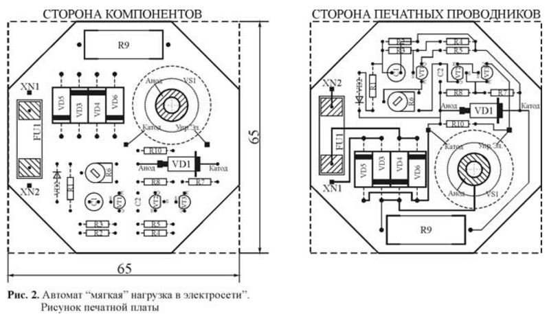
Construction and details. The machine is assembled on a printed circuit board (Fig. 2) from double-sided foil fiberglass 1,5 mm thick in the form of a regular octagon inscribed in a square with a side of 65 mm. You can, of course, use a round blank with a diameter of 70 mm. The printed circuit board is intended for installation in a standard network junction box with an internal diameter of 70 mm. Transistors VT1, VT2 can be any of the KT3107, VT3 - KT3102 series. We will replace the VD1 zener diode with D814G, KS512, KS515. Diode VD2 - any silicon. Thyristor VS1 can be from the series KU201, KU202 with indices K, L, M, N. Diodes KD226 with indices G, D, E. Fuse FU1 is installed on the holder.
Principle of operation. The electrical circuit of an improved version of the staircase lighting machine, supplemented by a microphone and a timer function, is shown in fig. 3. It uses the same thyristor brightness controller with phase-pulse control, but for the normal operation of the machine and the supply voltage, a chain of series-connected resistors R30-R31 is introduced into the controller, which sets the initial brightness of the incandescent lamp at the level of 10 ... 15%. This is necessary to obtain stable voltages "+5" and "+10V" of the power supply in standby mode. At the moment of closing the power circuit, the resistance of the filament of the incandescent lamp is maximum, and since ballast capacitors C16, C17 of relatively small capacity are introduced into the parametric stabilizer, the charging of the capacitor C15 does not occur immediately, but within tenths of a second. For this reason, the time constant of the integrating circuit R13-C10 must be slightly longer than the time for establishing the supply voltage "+5" to ensure reliable zeroing of the counter DD2 at the moment the power is turned on. After establishing the supply voltage "+5", at the input of the inverting element DD1.2 with a Schmitt trigger for some time (determined by the values of R13, C10), a logic zero level is maintained, which, after inversion by this element, resets the counter DD2. After the charging of the capacitor C10 is completed, it does not affect the operation of the device, since the VD5 diode is closed. After setting the counter DD2 to the zero state, a zero level appears at its output "Q12" (pin 1), which, inverted by the element DD1.3, opens the switching transistor VT1. The lower terminal of the resistor R24 is connected to the common wire and the capacitor C18 is charged. The brightness of the incandescent lamp increases to a maximum value, which is set by the resistance of the resistor R29. For the rating R29 indicated on the diagram, the maximum brightness value is about 80%. Thus, when the device is first turned on, the incandescent lamp burns with a maximum brightness of 80% for a specified period of time. A high output power of the regulator (up to 99%) can be provided only by turning it on according to the "three-terminal" scheme. For a staircase lighting machine, this is not important, since a high brightness of lighting is usually not required, but, if necessary, it is possible to compensate for the loss of brightness by installing a higher power incandescent lamp. At the same time, the “one” level from the output “Q12” (pin 1) of the counter DD2 enters the cathode of the diode VD6, biases it in the opposite direction and enables the operation of the generator assembled on the elements DD1.5, DD1.6, R19 ... R21, C11. Pulses of positive polarity are countable for DD2, which, upon reaching 2048 states, generates a "one" level at the output of the most significant bit "Q12" (pin 1). This level, being inverted by the element DD1.3, causes the generator to stop. The same level closes the transistor VT1 and puts the machine into standby mode. In this state, the minimum brightness of the glow of the incandescent lamp is determined by the position of the trimmer resistor R31 and can be selected in the range of 10 ... 50%. The microphone amplifier is made on the op-amp DA1.1 and DA1.2. Its total amplification factor can reach 5000, therefore, to trigger the machine from the microphone output, an alternating voltage with an amplitude of 1 mV is sufficient. The sensitivity of the amplifier can be adjusted by the resistor R5 so that the machine does not work from the sound of steps on the landing, but only to any voice command. In this case, you can set the brightness in standby mode, for example, 50%, and if it is necessary to receive additional lighting by the "owner" of the landing, give any voice command. To increase stability at high frequencies and eliminate self-excitation, capacitors C4, C6 are introduced into the microphone amplifier. Amplified alternating voltage from the output DA1.2 through the coupling capacitor C7 is supplied to the rectifier, assembled on the diodes VD1, VD2. The rectified voltage is smoothed by the capacitor C8 and fed to the reset pulse shaper, made on the elements DD1.1, DD1.2, C9, VD3, VD4, R11, R12. When the voltage on the capacitor C8 reaches the switching threshold of the element DD1.1 (approximately 2,6 V), a short positive pulse is generated at the output of the element DD1.2, with a duration of about 8 μs, which, each time an audible signal appears, resets the counter DD2 and restart the timer. A visual assessment of the elapsed exposure time (when setting the timer) is produced by the line of LEDs HL1 ... HL4 (HL1, HL2 - green, HL3 - yellow and HL4 - red). If you want to visually evaluate the elapsed exposure time at a distance, it is necessary to reduce the resistance of the resistors R15 ... R18 to 4,7 kOhm, and increase the capacitance of the ballast capacitors C16, C17 to 0,47 μF. The timer delay time can be increased to 3,5 hours by replacing the capacitor C11 with a larger one, with a rating of up to 2,2 microfarads, and the minimum delay can be changed by selecting the resistor R19. Another interesting feature of the microphone amplifier (DA1.1, DA1.2) should be noted. If you increase the values of the capacitors: C4=0,01 uF; C5=2,2uF; C6=6800 pF; C7 = 47 uF and install an automatic machine inside a closed space, then the amplifier will not respond to sound signals, but only to a change in air pressure even with silent opening and closing of doors.
Construction and details. The machine is assembled on a printed circuit board (Fig. 4) from double-sided foil fiberglass 1,5 mm thick from a square blank with dimensions of 78x78 mm. For installation in a standard network junction box of the KEM5-10-7 type, corners 13x13 mm in size are cut out in a square blank. The machine uses fixed resistors MLT-0,125, MLT-2 (R34), trimming resistors SP3-38b in horizontal design, ballast capacitors C16, C17 of type K73-17 with a rated voltage of 400V, the rest are non-polar - K10-17, oxide - K50-35 or imported. The microphone can be of type CZN-15E, MKE-332, MKE-333, MKE-389-1. In place of VD12, VD13, as in the previous version, D814G (D), KS512, KS515 can work. Transistors VT1, VT4 can be from the KT3102 series; VT2, VT3 - KT3107. Op-amp DA1 will replace TL072, TL082; IC DD1 KR1564TL2 (74HC14), containing six Schmitt triggers, replace CD40106, counter KR1561IE20 (CD4040) replace KR1564IE20 (74HC4040). Setting the second version of the device consists in setting the minimum brightness in standby mode using the resistor R31, the sensitivity of the microphone amplifier - R5 and the required time delay - R21. The response delay from the moment the sound signal or voice command appears can be increased by selecting capacitor C8. If, with an increase in the values of capacitors C16, C17 to 0,47 μF, the counter DD2 will not be clearly reset at the moment the power is turned on, it is necessary to increase the capacitance of the capacitor C10 to 4,7-10 μF. With an incandescent lamp power of more than 75 W, the thyristor must be installed on a heat sink. Literature
Author: Odinets A.L.
Artificial leather for touch emulation
15.04.2024 Petgugu Global cat litter
15.04.2024 The attractiveness of caring men
14.04.2024
▪ Samsung PRO Plus and EVO Plus Memory Cards ▪ External drive Western Digital My Book Duo 44 TB ▪ Medical masks with copper nanolayer
▪ section of the site Your stories. Article selection ▪ article Swing chair. Tips for the home master ▪ article Exams in which subject were canceled in Soviet schools in 1988? Detailed answer ▪ article Crawler of the hydraulic ash removal route. Standard instruction on labor protection ▪ article Coloring Tibetan sheepskins. Simple recipes and tips
Home page | Library | Articles | Website map | Site Reviews
www.diagram.com.ua |


 Leave your comment on this article: