|
|


 Arabic
 Bengali
 Chinese
 English
 French
 German
 Hebrew
 Hindi
Hindi Italian
 Japanese
 Korean
 Malay
Malay Polish
 Portuguese
 Spanish
 Turkish
 Ukrainian
 Vietnamese
|
ENCYCLOPEDIA OF RADIO ELECTRONICS AND ELECTRICAL ENGINEERING Universal warm start electronic ballast for T8 fluorescent lamps. Encyclopedia of radio electronics and electrical engineering
Encyclopedia of radio electronics and electrical engineering / Lighting The author proposes the design of an electronic ballast for T8 fluorescent lamps, assembled on a specialized ICB1FL02G microcircuit. The device is equipped with an active power corrector, provides protection against emergency modes and has seven different options for connecting lamps of different power. Electronic ballast - an electronic ballast, often called an electronic ballast, is used to ignite and maintain the operating mode of gas discharge lamps (in this case, fluorescent lamps). The advantages of an electronic ballast over a conventional choke and starter are obvious, such as the absence of lamp flicker at start-up, a higher power factor, a significantly lower luminous flux ripple factor, as well as lower cost, etc. Nowadays, almost every fluorescent lamp, whether office or home, is equipped with an electronic ballast. In terms of circuitry, mass-produced electronic ballasts can be divided into two categories. The first is a half-bridge converter with autostart on two powerful high-voltage transistors of the 13007 series with a passive power corrector. Ballasts of this type are the most inexpensive and common, operating at a frequency of 36...38 kHz. The second - more expensive electronic ballasts, assembled on specialized microcircuits, have an active power corrector and a "warm" start function. They usually have an oscillator frequency of 36...48 kHz and are distinguished by a very low light flux pulsation coefficient - 2...5%. For comparison: for a lamp switched on with a conventional choke and starter, the luminous flux pulsations are approximately 40 ... 60%, with a cheap electronic ballast - about 15%. The version of the electronic ballast on a specialized microcircuit will be discussed in this article. Main Specifications
The ballast is assembled on a specialized microcircuit-controller of electronic ballast for fluorescent lamps - ICB1FL02G, developed by Infineon. Ballasts on this chip are similar in circuitry to ballasts on International Rectifier chips, for example, IR2168, IR2166, but require fewer external elements and, as practice has shown, are more stable and reliable (this is the subjective opinion of the author). The scheme of the device is shown in fig. 1. Its main distinguishing feature is seven configurations (options) for connecting lamps: 1x18 (one T8 fluorescent lamp with a power of 18 W), 1x36, 1x58, 2x18, 2x36, 3x18, 4x18 (Fig. 2). A detailed description of the operation of the microcircuit is given in [1]. The operation of the ballast can be divided into three stages: preheating of the lamp cathodes, ignition and operating mode. Preheating is implemented as follows. Immediately after switching on, the clock generator of the microcircuit begins to operate at a frequency of about 125 kHz. After 10 ms, its frequency smoothly decreases to 65 kHz - this is the preheating frequency, which is set by resistor R22. This value is much higher than the resonant frequency of the L2C14 output ballast circuit, so the voltage applied to the cathodes of the lamps will not be sufficient to ignite them. The preheating of the lamps begins, the duration of which is set by the resistor R26 and is selected in the range from 0 to 2 s (in our case, 1 s). During this time, the frequency remains unchanged. During the preheating period, the cathodes of the lamps will be sufficiently heated by high-frequency current, and the gas in the lamps will begin to partially ionize. As a result, the subsequent ignition will take place in a less "stressful" mode for lamp filaments and with lower current surges through transistors VT2, VT3. The preheat function significantly, sometimes several times, increases the life of the fluorescent lamp.
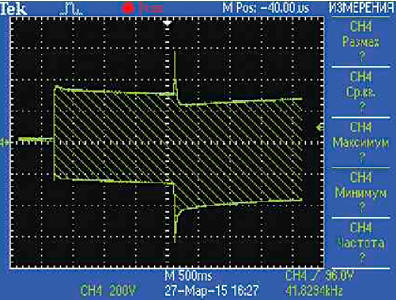
After a preheat time of the next 40 ms, the clock frequency of the microcircuit will begin to decrease again. As it approaches the resonant frequency of the L2C14 circuit, the voltage applied from the plates of the capacitor C14 to the cathodes of the lamps will begin to increase sharply and, when it reaches 600 ... 800 V, ignition will occur. If at this moment the voltage on the current sensor - resistor R27 reaches the threshold of 0,8 V, and this can happen, for example, when you try to turn on the ballast without load or if one of the lamps fails, the microcircuit controller will stop further reducing the frequency of the converter and start increasing it again , which, in turn, will cause a decrease in the voltage across the capacitor C14. This is done to avoid excessive current and voltage surge at the converter output. When the voltage drop decreases below 0,8 V across the resistor R27, the frequency will again decrease. This process may be repeated several times until a successful ignition signal is received. This signal is the appearance of a sinusoidal current with an amplitude of no more than 2,5 mA at the input LVS1 (LVS - Lamp Voltage Sense, pin 13) DA1 and a trapezoidal voltage with a swing of no more than 3,2 V at the input RES (RESTART, pin 12) DA1 . The maximum ignition time can be up to 235ms. In case of unsuccessful ignition of the lamps, the microcircuit will go into emergency mode and stop switching transistors VT2 and VT3. Upon successful ignition, DA1 will switch to operating mode, the clock generator frequency will decrease to the operating value, which is set by resistor R18. All three stages of ballast operation: warming up, ignition and operating mode are illustrated by the oscillogram in Fig. 3 (the oscilloscope is connected to pins 3, 9 of connector XS1). On fig. 4 shows the voltage waveform in the operating steady state with four 18 W lamps connected each.
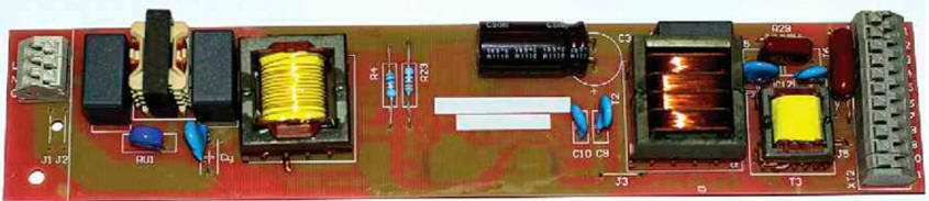
In operating mode, additional protective functions are activated: EOL (End Of Life) - the end of the lamp life, protection against operation in capacitive mode, protection against the rectifying effect of lamps. In the event of a sharp increase in current through the lamp, which may occur by the end of its service life, the current in the circuit will increase to 215 μA: plus power supply, R14, R16, R21, R23, R30, lamp filament, R17, R15, R13, R12, internal current sensor chip DA1. This will trigger the EOL protection and the ballast will turn off. If the positive and negative half-cycles of the current flowing through this circuit are not equal in amplitude, this means that the lamp is operating in rectifier mode. In other words, there is more current through the lamp in one direction than in the other. This effect is caused by premature wear of one of the cathodes of the lamp. In this case, the ballast also goes into emergency mode. If during the operation of the ballast the contact in the lamp circuit is broken, for example, due to a faulty lamp holder or a burnout of one of the filaments, the resistance of the circuit will increase sharply and the output stage will switch to capacitive operation, which, in turn, can cause resonance. In this case, the voltage at the RES input will exceed the level of 1,6 V, which will cause the protection to trip and turn off the ballast. In addition, the LVS1 and RES inputs of the DA1 chip serve to control the connection of lamps during the entire time the ballast is running. If one of the lamps is removed while the ballast is running, the ballast will turn off. The active power corrector is assembled on a transformer T1, a transistor VT1, a diode VD2 and a capacitor C5. Its purpose is to bring the shape of the consumed current as close as possible to the shape of the voltage, to reduce the phase shift between current and voltage, thereby minimizing reactive power. The principle of its operation is described in detail in [1] and [2]. A feature of this corrector is the ability to work both in Critical Conduction Mode (CCM) and in Discontinuous Conduction Mode (DCM). The divider R8-R11C6 is used to control the instantaneous value of the supply voltage and determine the closing time of the transistor VT1. The secondary winding of the transformer T1, connected through a current-limiting resistor R3 to the PFCZCD input (pin 7) DA1, is necessary to determine the moment when the current through the primary winding of the transformer reaches zero. As soon as this happens, an opening pulse will be applied to the gate of transistor VT1. Both windings of the transformer T1 must be in-phase. The microcircuit is powered at the first moment after switching on from the circuit R1, R2, R5. In the future - from the output stage through the stabilizer C12C13R28VD5VD6C10. To connect four lamps to the ballast, the microcircuit manufacturer recommends using two output ballast circuits connected in parallel, in each circuit there are two lamps connected in series [1]. But then the next problem arises. Even with a slight spread in the parameters of the output LC circuit, pairs of lamps can be ignited non-simultaneously, which is not very pleasant for perception. On the other hand, four lamps connected in series are quite problematic to ignite, since they do not have time to warm up sufficiently during preheating, and much more energy is required to ignite. In addition, we must not forget about the losses on the connecting wires. The solution was to leave one output circuit, but add a low-power auxiliary step-down transformer T2. It compensates for losses at the junction of the lamps, improves the heating of the lamps and facilitates their ignition. It has been experimentally established that the power of transformer T2 should be 8 ... .10% of the total power of the lamps, the transformation ratio is 20.30. When connecting 1x18, 2x18, 1x36 lamps to the ballast, the T2 transformer and coupling capacitors C11, C16 and C18 must be removed to avoid supplying excess power to the lamps. The documentation [1] provides the calculation of all the main elements of the ballast, with the exception of the output circuit L2C14. The inductance of the inductor L2 and the capacitance of the capacitor C14 are calculated as follows. Maximum lamp power (4x18 or 2x36) P=72 W, operating frequency selected f=41 kHz, ignition frequency fign=48 kHz [1], using a "warm" start, the optimal ignition voltage Uign≈700 V. From the energy ratio we obtain E = P/f = C U2/ 2, hence C14 = 2P/(fignUign2) = 2 72/(48 1037002) ≈ 6,1 nF. Of the available capacitors, a 6,8 nF capacitor was chosen. Now we determine the inductance of the inductor L2. The frequency is f = 1/(2π√LC), hence L2 = 1/(4π2C f2) = 1/(4π26,8 412106) = 2,2 mH. On the other hand, the inductance of the ballast choke must comply with the condition L2 = (UPete - ORл) topen/Iл , where UPete - supply voltage; Uл - operating voltage on the lamps (the operating voltage of an 18 W lamp is approximately equal to about 56 V, therefore, Uл=4 56=224 V); topen - transistor open time at f=41 kHz, topen ≈11,5 µs (according to [1]); Iл≈0,33 A - lamp operating current. From here L2 = (290 - 224) 11/330 = 2,2 mH. We determine the maximum current of the inductor L2, it will be equal to the current of the capacitor C14 at the time of resonance IL2 = Urez2π frezC = 700 2π 48 1036,8 10-9 = 1,4 A. We choose a magnetic core suitable for overall power, for example, EV25/13/13. Let us estimate the required gap g: g = (4 10-4π L IMax2)/(S B2), where S is the cross-sectional area of the magnetic circuit, m (for EV25/13/13 S=75 mm2); B - maximum induction, T; L - inductance, H; IMax - maximum current, A. Let's take the induction B = 0,22 T. Get g = (4 10-4π 2,2 10-31,42)/(75 10-60,222) = 1,5 mm. Calculate the number of turns N of the inductor L2: L=N2·ATL, hence N = √(L/AL) ; AL =(ToL0λ)/(μeg) where AL - inductance per turn (magnetic circuit with a gap), H; AL0 - inductance per turn (magnetic circuit without a gap, information from the reference book), H; λ is the length of the average power line of the magnetic circuit, mm; μe - initial magnetic permeability of the material of the magnetic circuit (information from the reference book). For magnetic core EV25/13/13, material N87 - AL0=2400 nH, λ=59 mm, μe= 1520. Hence AL = (2400 10-959 10-3)/(152 1,5 10-3) = 6,7 10-8 gn, N = √(2,2/10-3/6,7 10-8) = 181 turns. Let's check the maximum induction B = (IMaxμ0N)/g, where μ0 = 4π 10-7 H/m ; B = (1,4 4π 10-7181)/(1,5 10-3) = 0,212 T The inductor is wound with wire 4x0,2 mm (four wires with a diameter of 0,2 mm). If possible, it is desirable to divide the winding into sections. The device is assembled on a printed circuit board made of fiberglass laminated on one side. The printed circuit board drawing is shown in fig. 5. All elements for surface mounting are located on the side of printed conductors, all output elements are on the opposite side. The location of the elements is shown in fig. 6. Photos of the assembled device are shown in fig. 7 and fig. 8. Capacitor C14 - metal film, for a voltage of 1600 V, capacitors C11-C13 - metal film or disk ceramic for a voltage of 1000 V, capacitors C16, C18 - 100 V. Diodes VD2, VD4 - high-speed with a permissible reverse voltage of at least 600 V. Transistors FQD5N50 (VT1-VT3) can be replaced with SPP03N60C3 or similar. Transformer T1 is wound on an E25/13/7 magnetic core, material N27, non-magnetic gap 1,6 mm. The primary winding contains 184 turns of wire 4x0,2 mm, the secondary - 14 turns of wire with a diameter of 0,3 mm. Transformer T2 is wound on an E16/8/5 magnetic circuit, material N27, without a gap. Winding 1-2 contains 208 turns, windings 11 - 14, 6 - 7, 10 -13 - 24 turns each, windings 4 - 5, 8 - 9 - 12 turns each. The wire diameter of all windings is 0,18 mm. Frequency-setting resistors R18, R22, R26, it is desirable to choose with a tolerance of 0,5-1%. A properly assembled device usually starts working immediately and does not require adjustment.
Literature
Author: V. Lazarev
Machine for thinning flowers in gardens
02.05.2024 Advanced Infrared Microscope
02.05.2024 Air trap for insects
01.05.2024
▪ You need to quit smoking fast ▪ Raytheon laser systems for detecting and destroying drones ▪ Full color OLED WUXGA microdisplay ▪ One tenth of new laptops are with touchpads
▪ section of the website Residual current devices. Selection of articles ▪ article For passing. Popular expression ▪ article Do porcupines shoot their quills? Detailed answer ▪ Carlsbad Caverns article. Nature miracle ▪ article Electronic power switch-fuse. Encyclopedia of radio electronics and electrical engineering
Home page | Library | Articles | Website map | Site Reviews
www.diagram.com.ua |


 Leave your comment on this article: