|
|
ENCYCLOPEDIA OF RADIO ELECTRONICS AND ELECTRICAL ENGINEERING Battery powered lamp. Encyclopedia of radio electronics and electrical engineering
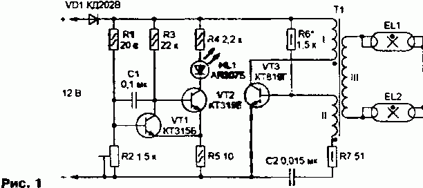
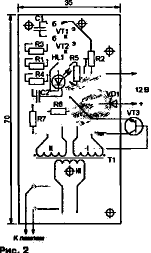
Encyclopedia of radio electronics and electrical engineering / Lighting Power outages have become a common occurrence in many parts of the country in recent years. The proposed lamp will help not to remain without light in such situations, in which one or two low-power fluorescent lamps are powered by a 12 V car or motorcycle battery. The device consists of widely used parts, its assembly will not take much time. The basis of the lamp, the scheme of which is shown in Fig. 1, - blocking generator on the transistor VT3. Resistor R7 limits the base current of the transistor. Diode VD1 protects the device from being connected to the battery power supply) in the wrong polarity. The sources of illumination are two fluorescent lamps (LDS) EL1 and EL2 connected in series with a power of 6 W from the Chinese lantern "ROBO". The luminaire has also been tested with single LDS with a power of 6 and 20 watts. According to the ratio of brightness and current consumption, the choice was made in favor of two six-watt ones. The low battery indicator is optional (all the elements included in it can not be installed on the board), but it is very useful especially when using a relatively small capacity battery (for example, a motorcycle battery). The indicator consists of LED HL1, transistors VT1, VT2, resistors R1-R5, capacitor C1 and is a Schmitt trigger. To achieve a sufficiently small width of the trigger hysteresis loop, the values of the resistors R1 and R3 had to be increased, and the positive feedback resistor R5 had to be decreased. Resistor R4 limits the current through the LED HL1. Capacitor C1 - noise suppression. While the battery is sufficiently charged, the transistor VT1 is open, since the voltage at its base is greater than the opening threshold. Transistor VT2 is closed - its base-emitter section is shunted by an open transistor VT1. LED HL1 off. As the battery discharges, the voltage at the base of the transistor VT1 decreases, the transistor VT1 starts to close. Due to the positive feedback, the process proceeds like an avalanche. As a result, the transistor VT1 closes completely, VT2 opens, the HL1 LED lights up. In standby mode, the indicator consumes no more than 1 mA, and after operation - approximately 5 mA. The entire LDS power unit is mounted on a printed circuit board made of one-sided foil-coated fiberglass (Fig. 2). It uses fixed MLT resistors of the power indicated in the diagram. Trimmer resistor R2 - multi-turn SP5-3. Capacitor C2 - K73-9, any small-sized one is suitable as C1.
Transistors VT1, VT2 - series KT315, KT3102 with any letter indices. Diode VD1 must be designed for a current not less than that consumed by the lamp from the battery, and it, in turn, depends on the power of the installed LDS. With one six-watt lamp, a diode from the KD226 series can be used here. LED HL1 - any color of glow, but better than red, the most suitable for signaling a situation requiring intervention. Of several transistors of the KT815, KT817, KT819 series, tested as VT3, the one indicated on the KT819G diagram ensured reliable switching on of the LDS. In addition, it has a fairly large margin for limiting current and voltage. The latter is especially necessary in case of accidental disconnection of the load from a running generator. For example, the KT815B transistor with a maximum collector-emitter voltage of 25 V worked properly until one of the wires connecting the LDS to winding III of the T1 transformer broke. The transistor was immediately broken. The magnetic circuit of the transformer T1 - B22 from ferrite 2000NM1. Windings I (9 turns of wire PEV-2 0,45) and I (10 turns of wire PEV-2 0,3) begin to wind simultaneously with two wires turn to turn. After the ninth, the end of the winding I is fixed in the slot of the frame, then the last turn of the winding II is wound up. The frame with the finished windings I and II is carefully impregnated with paraffin and wrapped with thin paper in two layers, ironing each with a hot soldering iron tip. As a result, the paper absorbs excess paraffin and adheres tightly to the wires of the windings, fixing them and providing the necessary insulation. Next, a high-voltage winding III is wound. For one LDS, it should contain 180, for two connected in series, - 240 ... 250 turns of wire PEV-2 0,16. The coils are laid in bulk, trying to distribute them as evenly as possible. It is necessary to ensure that those of them that are at the beginning and at the end of the winding do not touch each other. For example, it is highly undesirable to place both terminals of winding III in the same frame slot. The coil is once again impregnated with paraffin and inserted into the magnetic circuit, which is assembled with a gap of 0,2 mm between the "cups", using a paper or thin plastic gasket for this. Transformer T1 is attached to the board with a screw made of non-magnetic material, passed through the central hole of the magnetic circuit. This method, in contrast to assembly on glue, provides reliable fixation of the transformer on the board, and, if necessary, quick dismantling. The lamp is assembled on a wooden (plywood) base measuring 280x75x6 mm. In the upper part of the base, two LDSs are placed parallel to each other, in the lower part - a printed circuit board covered with an aluminum sheet casing. The casing provides holes for the HL1 LED and connecting wires, including two stranded ones with crocodile clips for connecting to the battery. Transistor VT3 is attached to the casing, using the latter as a heat sink. LDS is installed on two wooden bars glued to the base with a section of 15x10 mm. One of them is located at the upper edge of the base, the other is lower, at a distance equal to the length of the LDS without leads (215 mm). Under the conclusions of the lamps on the bars, contacts made of tin are installed. The contact on the upper bar simultaneously serves as a jumper between two LDS, and the terminals of the winding III of the transformer T1 are connected to the two on the lower bar. LDS is fixed with four screws screwed between their leads. In the contacts, it is necessary to drill holes for the screws in advance, and washers must be placed under the heads of the latter. This mounting method provides a reliable connection between the LDS and the transformer and allows you to replace the lamps without resorting to a soldering iron. For better light output, the base under the lamps is pasted over with a reflective film or foil. Before turning on the lamp for the first time, it is imperative to check the quality of the connection of the LDS with the winding III of the T1 transformer. A bad contact can lead to a breakdown not only of the VT3 transistor, but also of the transformer. If, after applying the supply voltage, there is not even a slight glow of the LDS, you should swap the conclusions of one of the windings I or II of the transformer T1 completely, VT2 opens, the HL1 LED lights up.
Machine for thinning flowers in gardens
02.05.2024 Advanced Infrared Microscope
02.05.2024 Air trap for insects
01.05.2024
▪ Apple creates 3D interface for iPhone and iPad ▪ NASA intern discovers exoplanet ▪ Uneducated flies live longer ▪ Freeform displays from Sharp
▪ site section Parameters of radio components. Article selection ▪ article Crocodile tears. Popular expression ▪ article When Was Aluminum Foil Invented? Detailed answer ▪ article Testing food products for acidity. Chemical experience
Home page | Library | Articles | Website map | Site Reviews www.diagram.com.ua |


 Arabic
 Bengali
 Chinese
 English
 French
 German
 Hebrew
 Hindi
Hindi Italian
 Japanese
 Korean
 Malay
Malay Polish
 Portuguese
 Spanish
 Turkish
 Ukrainian
 Vietnamese


 Leave your comment on this article: