Color and music setup with two-stage brightness control. Encyclopedia of radio electronics and electrical engineering

Encyclopedia of radio electronics and electrical engineering / Color and music installations, garlands
 Comments on the article
The dynamic range of incandescent lamps is much narrower than that of a piece of music. This leads to the fact that the color-music device tuned to the maximum incoming signal level (DMU) stops working at low signal levels. If the CMU is set to the minimum signal level, then at medium and maximum signal levels, the intensity of the glow of incandescent lamps is constant. As a result of this, a blinking effect occurs, which quickly tires the listener and does not correspond to the nature of the phonogram.
Special devices help to eliminate this contradiction - compressors and automatic gain controls, which allow narrowing the dynamic range of a musical work to the dynamic range of incandescent lamps (5 ... ... 10 dB). However, it is possible to match the dynamic ranges of the DMU and phonogram signals using multi-stage brightness control.
(click to enlarge)
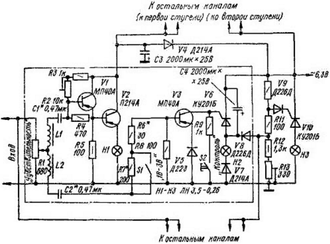
The diagram shows only the low-frequency channel of the DMU. The input signal, as usual, is divided by filters into the corresponding number of frequency channels. The filters of each channel are made of two independent LC circuits (L1C1 and L2C2). The first stage of the regulator is assembled on transistors V1 and V2, a parallel group of lamps H2 is included in the emitter circuit of transistor V1. The lamps of this group operate when the amplitude of the input signal changes from 0,5 to 3 V. This range can be slightly changed with the potentiometer R1. When the contacts of the switch S1 are open and the amplitude of the input signal increases by more than 3 V, the second DMU circuit (V3, V6, H2) is activated and the group of H2 lamps immediately turns on to full heat, displaying the amplitude signal spikes at the frequencies of the corresponding channel. In the closed position of switch S1, the lamps of this group begin to glow at an input signal level of 1 V. A backlight channel is assembled on the trinistor V10. The background channel works in conjunction with the first stage and turns off when the lamps of the second group of any of the channels are turned on.
The device is powered by a 6,3 V alternating current source. The input of the device is connected to the output of an audio frequency amplifier with a power of 4 ... 6 W. The Control button allows you to check the operability of the second stage and the background channel. The frequency band in the CMU is divided into three frequency channels: 100...350, 350...700, 700...2000 Hz. The filter coils of all channels are the same, have an inductance of about 1 H, contain 1000 turns each and are wound with PEV-2 0,15 wire on a K20x12x6 ring magnetic circuit made of 2000NM ferrite. Capacitors C1 and C2 in the channels have a capacity of 0,47; 0,1 and 0,02 uF, respectively, for each of the frequency channels. Screen device housing 400x300x120 mm. The screen is made of cellular transparent material. Closer to the screen are the lamps of the first stage, the side walls are pasted over with crumpled aluminum foil, and the back wall has a dark background, which changes the apparent depth of the screen. For a frequency channel of 100 ... ... 350 Hz, two lamps of the first stage and four lamps of the second are painted green, and one lamp of the second stage is red and yellow. For the frequency channel 350 ... 700 Hz, two lamps of the first stage and four lamps of the second are painted red and one lamp of the second stage is green and blue. For the frequency channel 700 ... 2000 Hz, three lamps of the first stage and six lamps of the second are colored blue, and two more lamps of the second stage are yellow. Background lamps (5 pieces) are colored differently and are placed over the entire area of the rear wall.
To configure the DMU, an audio frequency generator with a low-impedance output of 50 ohms is connected to its input. When the device is powered on, all background lamps should light up. The sensitivity of the channels is set to a minimum and the resistors R2 are adjusted until a weak glow of the lamps of the first stages is obtained. By adjusting the resistor R13, they ensure that when the channel button S2 is turned on, the second stage lamps turn on and the background lamps turn off. Then, having increased the sensitivity of the channels to the maximum, signals of various frequencies, with an amplitude of 1 and 3 V, are supplied from the generator and the operation of the DMU is checked. If necessary, select resistors R6 and R7 and filter capacitors C1 and C2.
Author: V.Gromov
 See other articles Section Color and music installations, garlands.
Read and write useful comments on this article.
<< Back
 Latest news of science and technology, new electronics:
Energy from space for Starship
08.05.2024
Producing solar energy in space is becoming more feasible with the advent of new technologies and the development of space programs. The head of the startup Virtus Solis shared his vision of using SpaceX's Starship to create orbital power plants capable of powering the Earth. Startup Virtus Solis has unveiled an ambitious project to create orbital power plants using SpaceX's Starship. This idea could significantly change the field of solar energy production, making it more accessible and cheaper. The core of the startup's plan is to reduce the cost of launching satellites into space using Starship. This technological breakthrough is expected to make solar energy production in space more competitive with traditional energy sources. Virtual Solis plans to build large photovoltaic panels in orbit, using Starship to deliver the necessary equipment. However, one of the key challenges ... >>
New method for creating powerful batteries
08.05.2024
With the development of technology and the expanding use of electronics, the issue of creating efficient and safe energy sources is becoming increasingly urgent. Researchers at the University of Queensland have unveiled a new approach to creating high-power zinc-based batteries that could change the landscape of the energy industry. One of the main problems with traditional water-based rechargeable batteries was their low voltage, which limited their use in modern devices. But thanks to a new method developed by scientists, this drawback has been successfully overcome. As part of their research, scientists turned to a special organic compound - catechol. It turned out to be an important component that can improve battery stability and increase its efficiency. This approach has led to a significant increase in the voltage of zinc-ion batteries, making them more competitive. According to scientists, such batteries have several advantages. They have b ... >>
Alcohol content of warm beer
07.05.2024
Beer, as one of the most common alcoholic drinks, has its own unique taste, which can change depending on the temperature of consumption. A new study by an international team of scientists has found that beer temperature has a significant impact on the perception of alcoholic taste. The study, led by materials scientist Lei Jiang, found that at different temperatures, ethanol and water molecules form different types of clusters, which affects the perception of alcoholic taste. At low temperatures, more pyramid-like clusters form, which reduces the pungency of the "ethanol" taste and makes the drink taste less alcoholic. On the contrary, as the temperature increases, the clusters become more chain-like, resulting in a more pronounced alcoholic taste. This explains why the taste of some alcoholic drinks, such as baijiu, can change depending on temperature. The data obtained opens up new prospects for beverage manufacturers, ... >>
| Random news from the Archive Charging wearable devices from the user's breath
08.12.2020
An international team of researchers led by scientists from the University of Pennsylvania (USA) has developed an elastic system that collects energy from human breathing and movement to charge "smart" wearable devices - for example, fitness bracelets.
According to the authors of the work, current versions of batteries and supercapacitors that power wearable and stretchable devices for monitoring and diagnosing health conditions have many disadvantages, including low energy density and insufficient elasticity.
An alternative to batteries are micro-supercapacitors, energy storage devices that can supplement or replace lithium-ion batteries in wearable devices. Of the advantages: micro-supercapacitors are small in size, have a high power density. On the downside, they have a "multi-layered" folded geometry, so these power sources don't stretch well, making them difficult to connect to wearable electronics.
Therefore, scientists decided to explore alternative device architectures. They found that the serpentine arrangement of micro-supercapacitor cells allows the configuration to stretch and bend at the bridges, the places that connect the cells. In this case, the main elements of micro-supercapacitors are less deformed.
To create this "lattice," the researchers used ultra-thin zinc-phosphorus nanosheets and three-dimensional laser-induced graphene foam, a highly porous, self-heating nanomaterial. The team also significantly improved the electrical conductivity of the charger. This proved that arrays of supercapacitors could efficiently store the energy needed to power a wearable device.
The developers went even further - and supplemented the new system with technology that converts the user's mechanical movement into electrical energy. This combination created a self-powered system.
"When we have this wireless charging module based on a triboelectric nanogenerator, we can collect energy from the user's movement - for example, bending the elbow, breathing or speaking," the authors note.
|
Other interesting news:
▪ Carbon nanotubes may be a strong carcinogen
▪ Across the English Channel on a jet hoverboard
▪ Intel Tunnel Falls silicon qubit processor
▪ Data can be stored in the dust
▪ Power Management ICs for OMAP35xx
News feed of science and technology, new electronics
 Interesting materials of the Free Technical Library:
▪ site section Lightning protection. Article selection
▪ article Criminal procedure. Lecture notes
▪ article Why didn't the President of the United States congratulate the four-time Olympic champion? Detailed answer
▪ article Loading and unloading, movement and storage of materials. Standard instruction on labor protection
▪ article Consumer electronics. Clocks, timers, relays, load switches. Directory
▪ article Refinement of the power supply SY-002-5-12. Encyclopedia of radio electronics and electrical engineering
Leave your comment on this article:
 All languages of this page
Home page | Library | Articles | Website map | Site Reviews

www.diagram.com.ua
2000-2024


 Arabic
 Bengali
 Chinese
 English
 French
 German
 Hebrew
 Hindi
Hindi Italian
 Japanese
 Korean
 Malay
Malay Polish
 Portuguese
 Spanish
 Turkish
 Ukrainian
 Vietnamese