|
|


 Arabic
 Bengali
 Chinese
 English
 French
 German
 Hebrew
 Hindi
Hindi Italian
 Japanese
 Korean
 Malay
Malay Polish
 Portuguese
 Spanish
 Turkish
 Ukrainian
 Vietnamese
|
ENCYCLOPEDIA OF RADIO ELECTRONICS AND ELECTRICAL ENGINEERING Low voltage LED power supply. Encyclopedia of radio electronics and electrical engineering
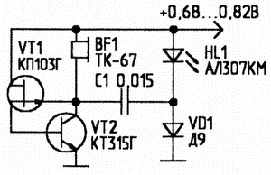
Encyclopedia of radio electronics and electrical engineering / Lighting LED sources of optical radiation in the visible range, due to design features, cannot glow at voltages below 1,6 ... 1,8 V. This circumstance sharply limits the possibility of using LEDs in devices with low-voltage (from one galvanic cell) power supply. The proposed LED emitters with low-voltage (0,1 ... 1,6 V) power supply can be used for voltage indication, data transmission via optical communication channels, etc. To power them, you can also use ultra-low voltage electrochemical cells, in which moistened soil or biologically active media serve as an electrolyte. The variety of low-voltage LED power supply schemes can be reduced to two main types of low-voltage conversion to high voltage. These are circuits with capacitive and inductive energy storage devices. Figure 1 shows the power supply circuit of the LED using the principle of doubling the supply voltage. The generator of low-frequency pulses, the repetition rate of which is determined by the chain R1-C1, and the duration - R2-C1, is made on transistors pn-p and npn structures. From the output of the generator, short pulses through the resistor R4 are fed to the base of the transistor VT3, in the collector circuit of which the red LED HL1 and the germanium diode VD1 are connected. A high-capacity electrolytic capacitor C2 is connected between the output of the pulse generator and the connection point of the LED and the germanium diode.
During a long pause between pulses (transistor VT2 is closed and does not conduct current), this capacitor is charged through VD1 and R3 to the power supply voltage. When a short pulse is generated, transistor VT2 opens. The negatively charged plate of capacitor C2 is connected to the positive power rail. Diode VD1 is locked. The charged capacitor C2 is connected in series with the power source and loaded on the chain: the LED is the emitter-collector junction of the transistor VT3. Since the transistor VT3 is unlocked by the same pulse, its emitter-collector resistance decreases. Thus, almost twice the supply voltage (excluding minor losses) is applied to the LED for a short time - its bright flash follows. After that, the process of charge-discharge of the capacitor C2 is periodically repeated. When using LEDs of the AL307KM type with a glow voltage of 1,35 ... 1,4 V, the operating voltage of the generator is 0,8 ... at which the current consumed by the device is 1,6 mA. Since the generator works in a pulsed mode, bright flashes of light are generated that attract attention. In the circuit, it is necessary to use a low-voltage, but rather bulky, high-capacity electrolytic capacitor C2. The sources of low-voltage LED power supply based on multivibrators are shown in Figs. 2, 3. The first of them is based on an asymmetric multivibrator that generates short pulses with a large interpulse pause. The energy storage - capacitor C3 - is periodically charged from the power source and discharged to the LED, summing its voltage with the supply voltage.
The generator (Fig. 3) provides, in contrast to the previous circuit, the continuous nature of the LED glow. The device is based on a symmetrical multivibrator and operates at higher frequencies. In this regard, the capacitances of the capacitors in this circuit are quite small. Of course, the brightness of the glow is noticeably reduced, but the average current consumed by the generator at a supply voltage of 1,5 V does not exceed 3 mA.
Capacitive-type voltage converters (with voltage doubling) for powering LED emitters can theoretically reduce the operating supply voltage by only up to 60%. The use of multi-stage voltage multipliers for this purpose is unpromising due to progressively increasing losses and a decrease in the efficiency of the converter. More promising in terms of further reducing the supply voltage are converters with inductive energy storage. It became possible to noticeably lower the lower limit of the supply voltage due to the transition to LC versions of generator circuits using inductive energy storage devices. A telephone capsule is used as an inductive energy storage in the first of the schemes (Fig. 4). Simultaneously with light radiation, the generator generates acoustic signals. When the capacitance of the capacitor increases to 200 microfarads, the generator switches to a pulsed mode of operation, generating intermittent light and sound signals. A somewhat unusual structure is used as an active element - a series connection of transistors of various types of conductivity covered by positive feedback.
The voltage converters for powering the LED in Figs. 5 and 6 are made on analogs of injection field-effect transistors. The first of the converters (Fig. 5) uses a combined inductive-capacitive circuit for increasing the output voltage, combining the principle of capacitive voltage doubling with obtaining an increased voltage on a switched inductance.
The simplest generator is based on an analog of an injection field-effect transistor (Fig. 6), where the LED simultaneously plays the role of a capacitor and is the load of the generator. The device operates in a narrow range of supply voltages, however, the brightness of the LED is quite high, since the converter is purely inductive and has a high efficiency.
Figure 7 shows a transformer-type generator for supplying LEDs with low voltage. The generator contains three elements, one of which is a light emitting diode. Without an LED, the device is the simplest blocking generator, and a rather high voltage can be formed at the output of the transformer. If you use an LED as a generator load, it starts to glow brightly. In the circuit, a ferrite ring F1000 K10x6x2,5 is used as a transformer. The windings of the transformer have 15 ... .20 turns of PEV wire with a diameter of 0,23 mm. In the absence of generation, the ends of one of the transformer windings are interchanged.
When switching to high-frequency germanium transistors such as 1T311, 1T313 and using unified pulse transformers such as MIT-9, TOT-45, etc., the lower limit of operating voltages can be lowered to 0,125 V. The supply voltage of all considered circuits, in order to avoid damage to the LEDs, should not exceed 1,6 ... 1,7 V. Author: M. Shustov, Tomsk; Publication: radioradar.net
A New Way to Control and Manipulate Optical Signals
05.05.2024 Primium Seneca keyboard
05.05.2024 The world's tallest astronomical observatory opened
04.05.2024
▪ 84" NEC MultiSync X841UHD display with 3840x2160 resolution ▪ Martian soil - radiation protection ▪ Graphene airgel is lighter than air
▪ section of the site Intercoms. Article selection ▪ article Children's disease of leftism. Popular expression ▪ article How long can the sun shine? Detailed answer ▪ article Abyssinian mustard. Legends, cultivation, methods of application ▪ article Focus with a set of holes. Focus Secret
Home page | Library | Articles | Website map | Site Reviews
www.diagram.com.ua |


 Leave your comment on this article: