|
|


 Arabic
 Bengali
 Chinese
 English
 French
 German
 Hebrew
 Hindi
Hindi Italian
 Japanese
 Korean
 Malay
Malay Polish
 Portuguese
 Spanish
 Turkish
 Ukrainian
 Vietnamese
|
ENCYCLOPEDIA OF RADIO ELECTRONICS AND ELECTRICAL ENGINEERING Large seven-element indicator. Encyclopedia of radio electronics and electrical engineering
Encyclopedia of radio electronics and electrical engineering / Lighting For electronic wall clocks, digital thermometers, etc. devices, the readings of which are desirable to be observed from a long distance, seven-element digital indicators of large sizes are required. If there are no indicators of the right size on sale, radio amateurs make them on their own, for example, they "gather" their constituent elements from incandescent lamps or LEDs. However, the first ones consume quite a lot of power and are short-lived, the second ones are quite suitable for these parameters, but for normal visual perception of signs they have to be installed every 5 ... 10 mm, so the number of LEDs is large. For example, to make an indicator from 72 mm elements (sign height is approximately 150 mm), you will need 70 LEDs (with a step of 8 mm).
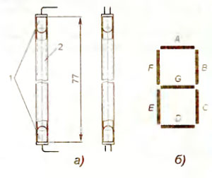
It is possible to reduce the number of LEDs several times by using them, for example, as described below. If two sufficiently bright LEDs 1 (Fig. 1, a) are inserted from the ends into segment 2 of a plastic tube for a cocktail, then a design will be obtained that can be successfully used in as an element of a homemade seven-element digital indicator. The appearance of the numbers displayed by the indicator, consisting of such elements, is shown in fig. 2.
The scheme of the device is shown in fig. 3. In fact, this is an indicator with a common anode. If it is necessary to have a common cathode, the polarity of all LEDs should be reversed. HL1-HL14 LEDs are super-bright green glows in transparent cases with a diameter of 5 mm. e.g. LDGL3333. LDGM3333, LDGM3343 from LIGITEK. The minimum current required for the simultaneous glow of all elements of the indicator is approximately 25 mA, the direct voltage drop on each element is about 6 V.
The indicator design is based on two printed circuit boards, the drawings of which are shown in fig. 4 On the first of them (left according to the figure), elements B and C are mounted on the second - E and F (according to the generally accepted marking shown in Fig. 1, b) Elements A, D, G and connecting jumpers are installed between the boards
The manufacture of the indicator begins with cutting tubes 77 mm long. Then the leads of the LEDs are formed - guided by their location on the boards shown in Fig. 4, the leads are bent at a right angle at a distance of approximately 2 5 ... 3 mm from the body (the HL14 cathode lead is bent at a distance greater than 5 mm). Finally, the housings of the LEDs are tightly inserted into the ends of the tubes, which were previously flared with a metal rod, so that the ends of the leads are directed in one direction. After mounting the elements, pieces of a flexible mounting wire are soldered to the printed circuit boards, which will serve as the outputs of the AG and +U indicator.
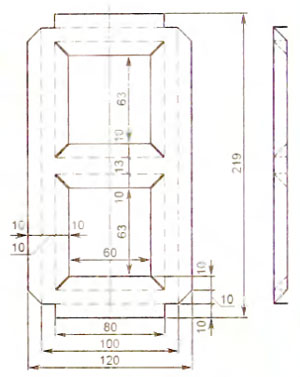
To avoid mutual illumination of the elements, the mounted boards are placed inside a box-shaped frame, the development of which is shown in Fig. 5 (size 80 mm and other dimensions adjacent to it are specified according to the actual distance between the boards) The blank is cut out of thin (0,25-0,4 mm thick) thick cardboard (for example, EV brand electric cardboard). The bend points are shown in the drawing with thin dashed lines, the cut points are thickened lines. In order for the inner walls to be held in a bent state, rectangular plates of the same material are glued between them. The frame with boards is placed in a case glued from opaque sheet polystyrene, in the side walls of which holes are drilled for the indicator leads. The internal dimensions of the case should be 1 ... Author: D. Mamichev, p/o Shatalovo, Smolensk region; Publication: radioradar.net
Machine for thinning flowers in gardens
02.05.2024 Advanced Infrared Microscope
02.05.2024 Air trap for insects
01.05.2024
▪ Miniature oscillators 32,768 kHz from Geyer ▪ A new kind of space balloon for space travel ▪ CIA considers using microwaves and irons for spying ▪ Electronic Willpower Trainer ▪ New fabric will keep you warm and cool
▪ section of the site Protection of electrical equipment. Article selection ▪ article by William James. Famous aphorisms ▪ article What is shock? Detailed answer ▪ Etna article. Nature miracle ▪ article Security system MICROALARM. Encyclopedia of radio electronics and electrical engineering ▪ article Coin through a bottle. Focus secret
Home page | Library | Articles | Website map | Site Reviews
www.diagram.com.ua |


 Leave your comment on this article: