|
|
ENCYCLOPEDIA OF RADIO ELECTRONICS AND ELECTRICAL ENGINEERING Attachment to the oscilloscope. Encyclopedia of radio electronics and electrical engineering
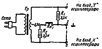
Encyclopedia of radio electronics and electrical engineering / Measuring technology A simple prefix, the schematic diagram of which is shown in fig. 1 allows you to evaluate the quality of transistors and semiconductor diodes, capacitors, resistors, potentiometers and inductors, check whether there are any breaks in the circuits, the health of switches, relays and transformers with winding resistance up to 100 kΩ.
When the set-top box is connected to the network and the Kn1 button is open, the voltage between terminals 2 and 3 will be equal to the voltage on the secondary winding of the transformer Tr, since the current does not flow through the resistance R1 and there is no voltage drop on it. If terminals 2 and 3 are short-circuited (shown by an arrow in the diagram), then all the voltage of the secondary winding will be applied to terminals 1 and 2. If they are opened and the calibration button Kn1 is pressed, then the voltage of the secondary winding will be equally distributed between terminals 1-2 and 2-3. The prefix is attached to the oscilloscope, as shown in Fig. 2. The internal sweep of the oscilloscope is turned off. By adjusting the movement of the electron beam across the screen, as well as the amplification of the horizontal and vertical channels with the button Kn1 closed, a line is obtained on the oscilloscope screen located at an angle of 45 ° to the horizontal (Fig. 2, a), along the length approaching half the diameter of the screen.
If you open the Kn1 button, and close clamps 2-3, a vertical line will appear on the screen (Fig. 2, b), if they are opened, a horizontal line will appear (Fig. 2, c). The element under test is connected to terminals 2-3. The nature of the image on the oscilloscope screen is determined by the dependence of the resistance of the element under test on the magnitude and polarity of the sinusoidal voltage supplied to it. semiconductor diodes. When testing a semiconductor diode, it is connected as shown in Fig. 3, a. In the case when the diode is of good quality, the image shown in fig. 3b; if the connection polarity is reversed, then the oscillogram will be reversed (Fig. 3, c). If the top of the corner on the screen is rounded, or one of its sides is much larger than the other, or the direction of the straight lines is very different from horizontal and vertical, then the diode should be rejected.
Silicon zener diodes are connected in the same way as all other diodes. When the stabilization voltage is below 10 V, a mark in the form of a vertical line will appear on the image (Fig. 3, d). Selenium rectifiers are connected in the same way as semiconductor diodes. A typical waveform is shown in fig. 3e. The tested selenium rectifier can be rejected if the angle on the screen has a very short or very flat vertical side. When tunnel diodes are connected, an image appears on the screen (Fig. 3, f) in the form of two almost vertical lines with a break in the middle. If we now increase the gain along the "X" axis, then the picture on the screen will change (Fig. 3, g). On fig. 3h shows how silicon controlled diodes are connected. The control electrode remains free. The image that appears in this case is shown in fig. 3, i. There may be a slight deviation of the line from a straight line. If the control electrode is grounded, the image will be different (Fig. 3, j). Transistors. The transistors to be tested are connected according to the circuit shown in fig. 4, a. The base is not connected to anything. A straight or slightly wavy horizontal line should appear on the screen. If the line is bent, then the transistor has unstable parameters. When there is a short circuit in the transistor, the line will be vertical.
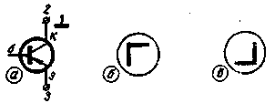
If you touch the base output to terminal 2, then an oscillogram should appear such as in Fig. 4, b (for p-n-p transistor) and as in fig. 4, c (for n-p-n). The connection of the base terminal with clamp 3 causes the opposite phenomenon (Fig. 4, b - for n-p-n and Fig. 4, c - for p-np). Suppose, in any of these two cases, the image will not look like a right angle. So the transistor is broken. If the image is strongly distorted, the parameters of the transistor are unstable. The deviation of the sides of the corner from the horizontal and vertical indicates poor quality transitions. Resistors and capacitors. Since the image corresponding to open terminals 2 and 3 (resistance is infinite) is a horizontal line, and closed (resistance is zero) - vertical, then the intermediate resistance value will correspond to . an image of a straight line with a certain angle of inclination. On fig. 5 shows a graph showing the dependence of the angle of inclination of a straight line, relative to the horizontal, on the resistance of a resistor connected between terminals 2 and 3.
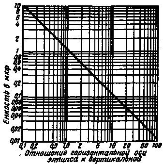
The central output of the potentiometer and one of the ends are connected between terminals 2 and 3. When the potentiometer knob is rotated, an image in the form of a rotating straight line should be observed on the oscilloscope screen. Unsmooth rotation of the straight line indicates poor quality of the moving contact. The resistance of a resistor can be determined using the graph in Fig. 5. The photoresistors are connected between clamps 2 and 3. If the sensitive layer of the photoresistor is closed from light, the image looks like a horizontal or slightly sloping straight line. The latter means that the dark resistance is high. When the photoresistor is illuminated, the straight line should take a position close to vertical. The resistance values can be determined using the graph (Fig. 5). The magnitude of the resistance can also be judged on the illumination. Before testing capacitors, it is necessary to calibrate the device, as described at the beginning of the article. After that, a capacitor is connected between terminals 2 and 3. A high-quality capacitor should correspond to the image in the form of an ellipse. Knowing the ratio of the lengths of the horizontal and vertical axes of the ellipse, it is possible to determine the capacitance of the capacitor from the graph (Fig. 6). With a capacitance of 1,1 uF, the ratio of the axes is 1, and the ellipse turns into a circle.
Inductors, transformers, relays. The inductor is connected to terminals 2 and 3. With an inductance of up to 5 H, the image will look like an ellipse, the major axis of which is tilted relative to the vertical. With an inductance value of about 5 H, the ellipse turns into a circle, and with an inductance greater than 5 H, the major axis of the ellipse is inclined to the horizontal. This method of measuring inductance is not particularly accurate, since the image on the screen depends on the turn-to-turn capacitance, winding resistance, etc. By comparing the image corresponding to the coil under test with the image from a known good coil, one can understand whether there are short-circuited turns or not. Since the very low resistance between terminals 2 and 3 gives a vertical line image on the screen, the attachment can also be used to test relays, switches, as well as to detect breaks in circuits, in transformer windings, etc. It should be noted that due to various phase distortion in the horizontal and vertical deflection amplifiers of the oscilloscope, there may be some bifurcation of lines on the screen. Using the described device, you can determine how much the capacitances of capacitors or resistances of resistors differ from the nominal value. Literature
Publication: N. Bolshakov, rf.atnn.ru
Machine for thinning flowers in gardens
02.05.2024 Advanced Infrared Microscope
02.05.2024 Air trap for insects
01.05.2024
▪ The hippocampus helps you navigate in space ▪ Innovative silicon supercapacitor ▪ Created a biodegradable transistor based on proteins
▪ section of the site Electricity for beginners. Article selection ▪ article by Abu Ali Hussein ibn Abdallah ibn Sina (Avicenna). Famous aphorisms ▪ article Why is the Michelin Bibendum tire symbol white instead of black? Detailed answer ▪ article Refueler. Standard instruction on labor protection ▪ article Extraordinary package. Focus Secret
Home page | Library | Articles | Website map | Site Reviews www.diagram.com.ua |


 Arabic
 Bengali
 Chinese
 English
 French
 German
 Hebrew
 Hindi
Hindi Italian
 Japanese
 Korean
 Malay
Malay Polish
 Portuguese
 Spanish
 Turkish
 Ukrainian
 Vietnamese


 Leave your comment on this article: