|
|


 Arabic
 Bengali
 Chinese
 English
 French
 German
 Hebrew
 Hindi
Hindi Italian
 Japanese
 Korean
 Malay
Malay Polish
 Portuguese
 Spanish
 Turkish
 Ukrainian
 Vietnamese
|
ENCYCLOPEDIA OF RADIO ELECTRONICS AND ELECTRICAL ENGINEERING Prefix on the tunnel diode. Encyclopedia of radio electronics and electrical engineering
Encyclopedia of radio electronics and electrical engineering / Measuring technology The use of swept frequency generators makes it easier and faster to tune the RF and IF channels of radios and TVs. Relatively simple swept frequency generators can be made on tunnel diodes. Basic information about the principle of operation of tunnel diodes is given in Radio, 1964, Nos. 11, 12, as well as in the literature cited at the end of the article. On fig. 1 shows diagrams of three variants of sweeping frequency generators based on tunnel diodes. These generators operate in relaxation mode.
In the variant, the scheme of which is shown in Fig. 1, a, the relaxation frequency of the tunnel diode D1 changes as a result of its attachment to the divider R1R2, to which a sawtooth voltage is applied. In this version of the generator, it is practically possible to obtain a one and a half to twofold change in frequency. The middle frequency can be moved in one direction or another by rotating the core of the L1 coil. In the generator, the circuit of which is shown in Fig. 1, b, a varicap D2 is used to swing the frequency, to which a control sawtooth voltage is applied. When used as D2 varicaps of the D901 type, one and a half times the frequency change can be obtained. The center frequency is moved in the same way as in the previous oscillator. Figure 1c shows a diagram of a magnetically controlled frequency swing generator. Coil L1 is wound on a ferrite core and placed in the air gap of the iron core of the control choke Dr1. A sawtooth current and a direct current flow through the winding of the inductor Dr1. By changing the magnitude of the DC bias current, you can change the average frequency of the generator by four to five times, and by changing the amplitude of the sawtooth current, you can change the frequency deviation. This version of the generator is the most convenient, since the installation of the average frequency and deviation is carried out electrically. Since all three versions of the generators operate in the relaxation mode, their outputs, in addition to the fundamental frequency, also contain higher harmonics. When setting up TV nodes, in addition to the fundamental frequency, one of the harmonics can also be used, since the bandwidth of the RF and IF amplifiers of TVs is less than the distance between the harmonics. Note that the degree of frequency deviation depends on the harmonic used. So, at the second harmonic, the absolute change in frequency is twice as large as at the fundamental frequency, at the third harmonic - three times, etc. Sweep generators must have a constant output voltage amplitude within the frequency deviation band and create a linear frequency scale on the oscilloscope screen. When a load is connected to the generator output, these parameters should change as little as possible. For all generator circuits shown in fig. 1, satisfactory linearity of the frequency scale can be obtained by adjusting the shape of the control voltages and currents. It is relatively easy to obtain good linearity of the frequency scale and a decent amplitude of the output voltage over the entire frequency deviation range using the circuit shown in Fig. 1c. Reducing the dependence of the generation frequency and the linearity of the frequency scale on the load connected to the generator output can be achieved in the simplest way by removing the output voltage from the Divider (R3R4 in Fig. 1, a; 1, b; 1, c). You can also install a buffer stage between the generator and the tuned node on a high-frequency transistor connected according to a common base circuit. Figure 2 shows a practical diagram of the simplest attachment to an oscilloscope for observing on the screen of its cathode ray tube the frequency response of the IF amplifier of the TV image. The frequency swing is carried out by periodically changing the power mode of the tunnel diode AI301B (D2). The prefix is powered by a cheeky winding of a power transformer or from some other source of alternating voltage 6-7 V, 50 Hz.
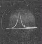
The voltage ripples on the capacitor of the smoothing filter C1 of the half-wave rectifier assembled on the diode D226B (D1) have a sawtooth shape, since the capacitor C1 is quickly charged through the diode D1 and is relatively slowly discharged through the circuits that load the rectifier. These pulsations feed the generator, the circuit of which is no different from that shown in Fig. 1c. If necessary, the average frequency of the generator can be changed by moving the ferrite core of the coil L1. The prefix has three outputs of frequency-modulated voltage (FM). Output 1 is used to tune the resonant circuits, while outputs 2 and 3 are fed to the input of a tunable image IF amplifier. The frequency deviation depends on the amplitude of the voltage ripple across the capacitor C1. The capacitance of this capacitor is selected in such a way as to ensure simultaneous overlapping of frequencies from 22 to 42 MHz. To obtain a convenient horizontal image scale for observation, adjust the gain of the horizontal deflection channel of the oscilloscope. The set-top box uses one of the simplest ways to obtain a sliding frequency mark. It is as follows. A generator is assembled on the P416 (T1) transistor, the frequency of which can be changed using the capacitor C5, ranging from 22 to 42 MHz. The voltage from the output of this label generator is fed through capacitor C7 to a detector assembled on a D2B (D3) diode and connected to the output of a tunable IF image amplifier. With the help of this detector, a beat signal is selected between the frequencies of the sweeping frequency generator on diode D2 and the frequency generator. marks on transistor T1. As a result, a characteristic amplitude mark stands out on the image of the frequency response observed on the oscilloscope screen (Fig. 3).
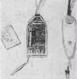
In the oscillating frequency generator of the set-top box, no measures were taken to disrupt the generation during the reverse motion of the horizontal beam. Therefore, a repeated image of the frequency response may appear on the right side of the CRT screen of the oscilloscope. It occupies approximately 15% of the length of the horizontal scan, and by adjusting the horizontal offset, it can be brought out of the tube screen. Structurally, the attachment is made in the form of two small probes (Fig. 4). One probe contains a sweeping frequency generator, and the other probe contains a detector and a frequency mark generator (details within the dashed rectangles in Fig. 2). This allows you to connect probes to a custom node with short wires (no more than 2-3 cm long). Coil L1 is wound without a frame on a mandrel with a diameter of 3 mm, in one layer turn to turn with PEL wire 0,7 mm and has 16-20 turns. Inside the coil is a 600NN ferrite core with a diameter of 2,8 mm and a length of 12 mm. The L2 coil is wound on a frame with a diameter of 8 mm (from the Record TV) in one layer turn to turn and contains 10 turns of 0,26 mm PELSHO wire. Coil core - SCR-1 type.
To calibrate the frequency mark generator, it is necessary to apply a signal from the GSS to the detector input through a 3-10 kΩ resistor. If the frequencies of the GSS and the frequency label generator are equal, zero beats will be observed on the screen of the cathode ray tube of the oscilloscope. To reduce the influence of the tuned circuit on the frequency of the oscillator of the swept frequency of the attachment, it may be necessary to use the buffer stage mentioned above. Literature 1. N. N. Goryunov, A. F. Kuznetsov, and A. A. Eksler, Circuits based on tunnel diodes. M., "Energy", 1965.
Authors: V. Gorbenko, E. Gorbenko, V. Mironov; Publication: N. Bolshakov, rf.atnn.ru
Machine for thinning flowers in gardens
02.05.2024 Advanced Infrared Microscope
02.05.2024 Air trap for insects
01.05.2024
▪ When the phone is life-threatening ▪ Augmented Reality Safety Helmet
▪ website section LEDs. Article selection ▪ article Famous people. Crosswordist's Handbook ▪ article What do fish eat? Detailed answer
Home page | Library | Articles | Website map | Site Reviews
www.diagram.com.ua |


 Leave your comment on this article: