|
|


 Arabic
 Bengali
 Chinese
 English
 French
 German
 Hebrew
 Hindi
Hindi Italian
 Japanese
 Korean
 Malay
Malay Polish
 Portuguese
 Spanish
 Turkish
 Ukrainian
 Vietnamese
|
ENCYCLOPEDIA OF RADIO ELECTRONICS AND ELECTRICAL ENGINEERING The light turns off automatically. Encyclopedia of radio electronics and electrical engineering
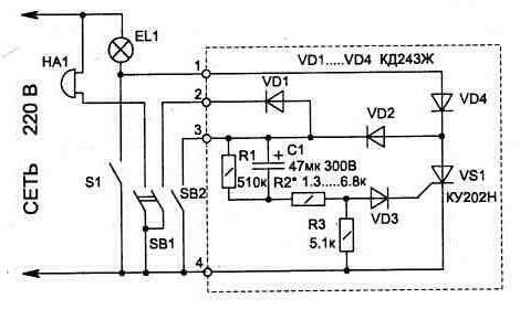
Encyclopedia of radio electronics and electrical engineering / Clocks, timers, relays, load switches This device is intended for use in the hallway of the apartment to automatically turn off the light 30..90 seconds after it is turned on with the SB1 (bell) or SB2 (inside the apartment) button. This time is enough to undress. Scheme, fig. 1.3, consists of a thyristor VS1, which will be in the open state for the time that the capacitor C1 is charging. The SB2 button can be installed next to the S1 light switch already in the apartment (the switch is convenient to use if you need light for a long time, for example, when cleaning up). The SB1 button is located outside the door and is a bell. When you click on it, the bell will ring and the light in the hallway will turn on for the time interval set during the setup, which will allow you to approach the door in the light. When the machine circuit is operating in lighting mode, the EL1 lamp will glow half-heartedly, since it operates on one half-wave of the mains voltage, but this is quite enough for lighting, and you can increase the brightness by increasing the power of the light bulb.
If desired, the circuit can be easily supplemented with another button - SB3 (connected in parallel with the SB2 button), which will be connected to the door and turn on the light when it is opened. The device could also find other uses, such as turning on a light in a basement. In this case, the SB1 button and the bell are not needed, and the lighting operation time can be increased by using a larger capacitor C1 (a capacitor of the K50-29 type for 300 V is used in the circuit) or by choosing a resistor R2. For stable operation of the circuit, the leakage current at the capacitor must be minimal. It is convenient to use any two-section light switch as an SB2 button, modifying one section to use it as a button. To do this, porous rubber is placed under the moving contact, which will not allow one section of the switch to be in a fixed state after pressing it. The existing call button can be modified by adding another contact to it, but if you have a relay with an operating voltage of 220 V, you can get by with one group of contacts. In this case, the relay turns on in parallel with the bell and, when it is triggered, its contacts (working instead of the second group of button contacts) discharge C1. The topology of the printed circuit board and the arrangement of elements on it is shown in fig. 1.4.
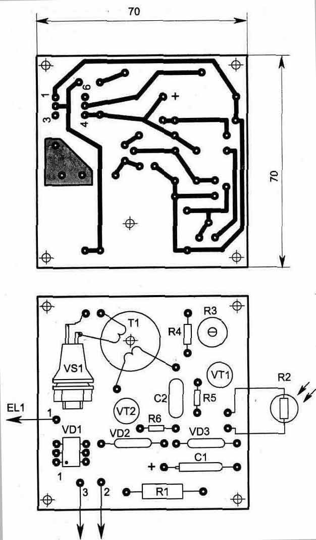
Compared to other published devices of a similar purpose, this circuit has smaller dimensions, does not contain scarce parts, and is easier to manufacture and connect. Sometimes you want to have a constant backlight, for example in the hallway. The backlight does not consume much energy (7 ... 15 W), but it is more economical if it works only at night. Turning the backlight on and off manually is not always convenient. Moreover, this can be successfully performed by automation. The electrical circuit of the automatic switch is shown in fig. 1.5. It consists of an amplifier (VT1) of the signal from the photosensor R2, a pulse generator on a unijunction transistor VT2 and a triac switch VS1.
The photoresistor, depending on the illumination, changes its resistance from 1 kOhm (at maximum illumination) to hundreds of kOhm (in the dark). This signal is amplified by the transistor VT1, which, as a rule, is saturated or closed - it depends on the illumination of the sensor R2. If the transistor VT1 is closed, then the generator works on the transistor VT2. The principle of operation of the generator is based on the property of a unijunction transistor to discharge capacitor C2 through base 1 when the voltage on it exceeds a threshold value (base 2). The periodic discharge of the capacitor C2 through the winding 1 of the transformer generates the opening pulses of the triac VS1 in the secondary winding. The load of the triac can be a lamp with power from 5 to 2000 W. The control circuit itself consumes no more than 1,3 W and has a transformerless power supply to reduce the size. For normal operation of the circuit, it is necessary that the photosensor be located remotely from the illumination zone. The desired sensitivity of the circuit to illumination is set by resistor R3. Parts used in the device: R2 type SF2-19 (FSK-1), R3 - SP4-1, C1 - K52-1B for 63 V, C2 - K10-17. Zener diodes VD2, VD3 can be replaced with D814B, V, Transformer T1 is wound with a PELSHO wire with a diameter of 0,18 mm on an M4000NM1 ferrite ring of size K16x10x4 mm and contains 1 - 80 turns in the winding, 2 - 60 turns. Round the sharp edges of the ring frame with a file before winding. The topology of the printed circuit board for the circuit and the location of the elements is shown in fig. 1.6. The radiator for the triac is necessary when it is working on a load with a power of more than 1000 watts. The case can be any, from dielectric materials.
Publication: cxem.net
Machine for thinning flowers in gardens
02.05.2024 Advanced Infrared Microscope
02.05.2024 Air trap for insects
01.05.2024
▪ Biochemical Reboot of the Eye: Treating Blindness
▪ section of the site for those who like to travel - tips for tourists. Article selection ▪ article In life there is always a place for a feat. Popular expression ▪ article Which scientist took a fee from those who wanted his autograph? Detailed answer ▪ article Handyman. Job description
Home page | Library | Articles | Website map | Site Reviews
www.diagram.com.ua |


 Leave your comment on this article: