Acoustic relay. Encyclopedia of radio electronics and electrical engineering

Encyclopedia of radio electronics and electrical engineering / Clocks, timers, relays, load switches
 Comments on the article
I present to your attention an acoustic relay. This circuit is quite simple even for beginners, it has only one microcircuit, one transistor, several capacitors, resistors and two relays.
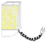
It all started with the fact that I have a lamp hanging on the wall in my country house, and when I go up to my 2nd floor late in the evening, it is difficult to turn on this lamp in the dark until you reach it :-). Based on this, the idea came to my mind to assemble such a thing that would turn on the light with a clap, and turn it off at the second clap.
I did not come up with this scheme myself, but simply joined two designs into one. It turned out pretty compact! And I decided to shove my creation right into the lamp, or rather, where the electronics of this lamp used to be. There was a lamp brightness control, and now an acoustic relay. Who did not understand what kind of lamp this is, see the picture:
Relay working principle
Let's start from the moment when a beep sounded in the microphone. The microphone, being the sensor of the device, converted the sound of a clap into an el. a signal that enters through the capacitor C1 to the input of the K157UL1A microcircuit, which is a preamplifier. Further, the amplified signal from the microcircuit is fed through the capacitor C6 to the cascade assembled on the transistor VT1. It is both an AC voltage amplifier and a DC amplifier. From the collector of the transistor VT1, the signal goes to the relay K1, which turns on, but not for long, it depends on the duration of the sound signal. This time is enough for the contacts of relay K1 to close and send a signal to the trigger made on relay K2. When the trigger turns on, relay K2 is activated, which turns on the load with some contacts, and controls the trigger with others. The correct operation of the trigger is achieved by selecting the resistance of resistors R8 and R9.
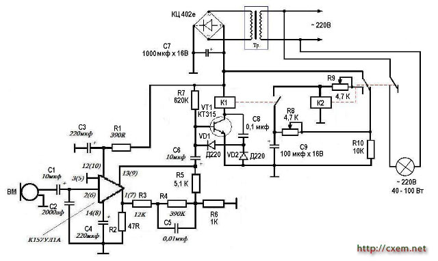
(click to enlarge)
Acoustic relay setting
At the first clap, the lamp should light up, and at the second clap, it should go out. If it lights up with a pop, and immediately goes out after it, then the current flowing through the resistor R9 and the winding of the relay K2 is lower than the release current. In this case, you need to twist the variable resistor R9. This can also be observed: the lamp turns on, but does not turn off. This indicates that the current flowing through the resistor R8 and the relay winding K2 is higher than the release current, and it holds the relay armature. So you need to twist the resistor R8.
Download file printed circuit board in LAY format
Authors: Tera (Dmitry), dmitryter89 [dog] yandex.ru, Sergey Ilyushkin; Publication: cxem.net
 See other articles Section Clocks, timers, relays, load switches.
Read and write useful comments on this article.
<< Back
 Latest news of science and technology, new electronics:
Artificial leather for touch emulation
15.04.2024
In a modern technology world where distance is becoming increasingly commonplace, maintaining connection and a sense of closeness is important. Recent developments in artificial skin by German scientists from Saarland University represent a new era in virtual interactions. German researchers from Saarland University have developed ultra-thin films that can transmit the sensation of touch over a distance. This cutting-edge technology provides new opportunities for virtual communication, especially for those who find themselves far from their loved ones. The ultra-thin films developed by the researchers, just 50 micrometers thick, can be integrated into textiles and worn like a second skin. These films act as sensors that recognize tactile signals from mom or dad, and as actuators that transmit these movements to the baby. Parents' touch to the fabric activates sensors that react to pressure and deform the ultra-thin film. This ... >>
Petgugu Global cat litter
15.04.2024
Taking care of pets can often be a challenge, especially when it comes to keeping your home clean. A new interesting solution from the Petgugu Global startup has been presented, which will make life easier for cat owners and help them keep their home perfectly clean and tidy. Startup Petgugu Global has unveiled a unique cat toilet that can automatically flush feces, keeping your home clean and fresh. This innovative device is equipped with various smart sensors that monitor your pet's toilet activity and activate to automatically clean after use. The device connects to the sewer system and ensures efficient waste removal without the need for intervention from the owner. Additionally, the toilet has a large flushable storage capacity, making it ideal for multi-cat households. The Petgugu cat litter bowl is designed for use with water-soluble litters and offers a range of additional ... >>
The attractiveness of caring men
14.04.2024
The stereotype that women prefer "bad boys" has long been widespread. However, recent research conducted by British scientists from Monash University offers a new perspective on this issue. They looked at how women responded to men's emotional responsibility and willingness to help others. The study's findings could change our understanding of what makes men attractive to women. A study conducted by scientists from Monash University leads to new findings about men's attractiveness to women. In the experiment, women were shown photographs of men with brief stories about their behavior in various situations, including their reaction to an encounter with a homeless person. Some of the men ignored the homeless man, while others helped him, such as buying him food. A study found that men who showed empathy and kindness were more attractive to women compared to men who showed empathy and kindness. ... >>
| Random news from the Archive Solar-powered helicopter makes first flight
20.09.2016
In the US, students at the University of Maryland tested the first solar-powered helicopter. A four-rotor helicopter equipped with a large number of solar panels. He stayed in the air for more than nine seconds. At first glance, not a very significant result, but it is worth remembering that the first flight of the Wright brothers lasted 12 seconds. At the same time, the height of its flight was a little more than 30 cm.
Previously, the same team made the longest flight of a pedal-powered helicopter in history. By the way, students partially used preliminary drawings for their new development.
"In seven years, this project has come a long way - from mechanical power to clean energy. We overcome the barriers of all types of aviation with a single airframe, modifying and refining the design," said University of Maryland doctoral student William Staruk.
|
Other interesting news:
▪ Playing with other children affects language learning
▪ Sony audio system with CarPlay
▪ Two mushrooms on chocolate
▪ new acacia
▪ Hamster sleeps - telomeres grow
News feed of science and technology, new electronics
 Interesting materials of the Free Technical Library:
▪ section of the site Videotechnique. Article selection
▪ article And you, friends, no matter how you sit down ... Popular expression
▪ article What is the function of the ears in addition to hearing? Detailed answer
▪ article Wiping glass, walls and vacuuming. Standard instruction on labor protection
▪ article Review of geothermal resources. Encyclopedia of radio electronics and electrical engineering
▪ article Who's there? Focus secret. Focus Secret
Leave your comment on this article:
 All languages of this page
Home page | Library | Articles | Website map | Site Reviews

www.diagram.com.ua
2000-2024


 Arabic
 Bengali
 Chinese
 English
 French
 German
 Hebrew
 Hindi
Hindi Italian
 Japanese
 Korean
 Malay
Malay Polish
 Portuguese
 Spanish
 Turkish
 Ukrainian
 Vietnamese