|
|
ENCYCLOPEDIA OF RADIO ELECTRONICS AND ELECTRICAL ENGINEERING Multi-limit time relay. Encyclopedia of radio electronics and electrical engineering
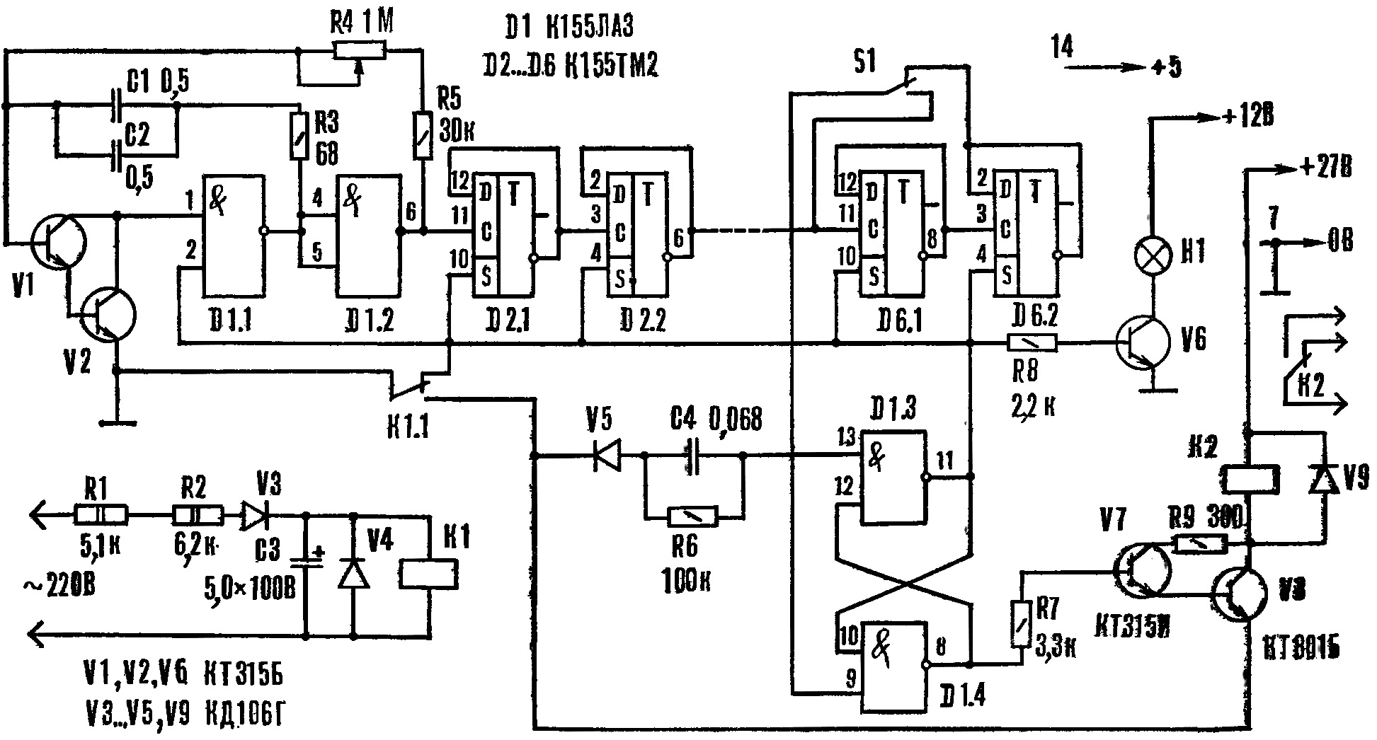
Encyclopedia of radio electronics and electrical engineering / Clocks, timers, relays, load switches The time relay, offered to the attention of readers, is used in automation devices in production and at home. The device is simple in design, has small dimensions, is reliable in operation, but its main feature is a large exposure range. Building an electronic time relay based on the principle of charge-discharge of a capacitor for exposures of more than 10 minutes is a difficult task. A high-resistance discharge circuit is subject to climatic factors (especially humidity), and if special measures are not taken, its stability is not high. The time relay, which uses a reference oscillator with frequency dividers and a decoder, is less susceptible to external influences. Therefore, such devices, which have significantly higher stability, can be built for shutter speeds of tens and hundreds of hours. However, it is difficult to manufacture such devices ourselves. The design, which is described in this article, combines the advantages of the mentioned devices and at the same time is available for repetition in amateur conditions. Schematic diagram of the time relay is shown in Figure 1. Transistors V1 and V2 with elements D1.1 and D1.2, capacitors C1 and C2, resistors R3, R4 and R5 form a generator; its frequency is set by a variable resistor R4. The generator output is connected to a frequency divider assembled on integrated circuits D2 - D6. From its output, the signals are sent to one of the inputs of the RS flip-flop assembled on elements D1.3 and D1.4. The other trigger input is connected to the trigger circuit.
One output of the RS flip-flop is connected through the transistor V6 to the indicator lamp H1, and the second through the transistors V7 and V8 to the relay K2. A triggering alternating voltage of 220 V is supplied through quenching resistors R1 and R2, diodes V3 and V4 and capacitor C3 to relay K1. In the initial state, when there is no starting voltage, contact K1.1 closes the generator, and it does not work. The frequency divider triggers are also in their original position: signal lamp H1 is off. Relay K2 is de-energized, although a high voltage level is applied to the base of transistor V7 (the emitter of V8 is disconnected from the "common" wire). When an input signal is received, relay K1 is activated and its contacts K1.1 are switched. At this moment, the RS-flip-flop changes its state to the opposite - at pin 11 of the D1.3 element, the voltage level becomes high, and at pin 8 D1.4 - low. The signal lamp H1 lights up, but the relay K2 remains de-energized, because the base of V7 has a low voltage level. The generator generates pulses that are fed to the frequency divider. With the advent of a low level at the output of the last element of the frequency divider, the RS flip-flop returns to its original state - at pin 11 of the D1.3 element it becomes low, and at pin 8 D1.4 it is high. The generator is braked, the lamp H1 goes out, and the relay K2 is activated (contacts K1.1 remain closed until the trigger voltage disappears). The device delays the arrival of the actuating voltage relative to the trigger voltage for the time of the set delay. It is set by the generator frequency using the resistor R4, as well as the scale switch S1. It is clear that the higher it is, the shorter the exposure time, and the greater the division factor of the frequency divider, the longer it is. The oscillator frequency can be tuned smoothly over a wide range, and the division factor can be jumped 4 times. The relay scale corresponds to 6 minutes, and when S1 is closed, it becomes equal to 1,5 minutes. To build a time relay with a delay of 24 minutes, it is enough to add one more K155TM2 microcircuit. Thus, the addition of one microcircuit increases the exposure time by 4 times. At the same time, the capacitance of the capacitors C1, C2 or the resistance of the resistor R4 should not be increased, since the stability of the first pulse of the generator worsens. A properly assembled device starts working immediately. The adjustment is reduced to the graduation of the scale, which is almost uniform when using a linear resistor (R4). Graduation is easy to perform if, after the first element of the frequency divider, measure the pulse duration and multiply by the division factor of the remaining part of the divider. During measurements, pin 9 of element D1.4 is turned off and the generator is started. This calibration method significantly reduces the time for this operation, since it is not necessary to wait until the maximum exposure period ends. After graduating, the relay circuit is restored. An electronic stopwatch is connected to terminal 11 of element D1.3 and the correctness of the scale graduation is additionally checked. The time relay, assembled on the K155 series microcircuits, is sensitive to interference penetrating the power circuits. Therefore, they must be blocked by capacitors.
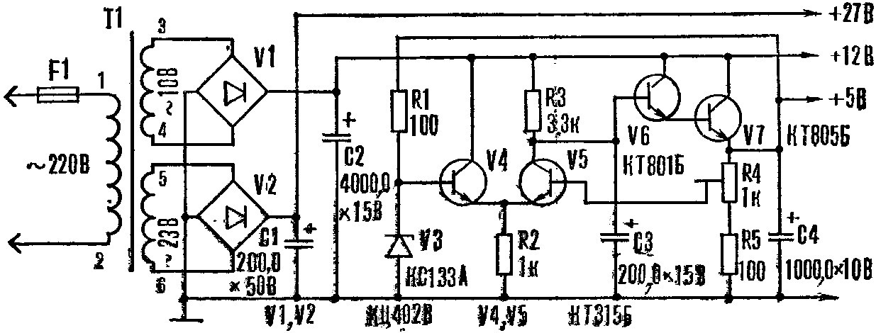
The power supply, the diagram of which is shown in Figure 2, is designed for a set consisting of six relays. T1 is made on the core from the television transformer TVK-110. The primary winding (pins 1-2) is wound with PEV-2 0,12 wire and contains 1760 turns, the secondary (pins 3-4) has 90 turns of PEV-2 0,71 wire, the third (pins 5-6) - 200 turns of wire PEV-2 0,21. Author: O. Lazarenko
Machine for thinning flowers in gardens
02.05.2024 Advanced Infrared Microscope
02.05.2024 Air trap for insects
01.05.2024
▪ The tallest statue in the world ▪ Clean fuel generated by photosynthesis
▪ section of the site Interesting facts. Selection of articles ▪ Mephistopheles article. Popular expression ▪ article Is it safe to say that quick-raised food is not considered dropped? Detailed answer ▪ article Locksmith for the operation and repair of gas equipment (VBGO). Job description ▪ article Dutch lacquer Elemi for oil paintings. Simple recipes and tips ▪ article Universal power supply. Encyclopedia of radio electronics and electrical engineering
Home page | Library | Articles | Website map | Site Reviews www.diagram.com.ua |


 Arabic
 Bengali
 Chinese
 English
 French
 German
 Hebrew
 Hindi
Hindi Italian
 Japanese
 Korean
 Malay
Malay Polish
 Portuguese
 Spanish
 Turkish
 Ukrainian
 Vietnamese


 Leave your comment on this article: