|
|


 Arabic
 Bengali
 Chinese
 English
 French
 German
 Hebrew
 Hindi
Hindi Italian
 Japanese
 Korean
 Malay
Malay Polish
 Portuguese
 Spanish
 Turkish
 Ukrainian
 Vietnamese
|
ENCYCLOPEDIA OF RADIO ELECTRONICS AND ELECTRICAL ENGINEERING Automatic lighting control. Encyclopedia of radio electronics and electrical engineering
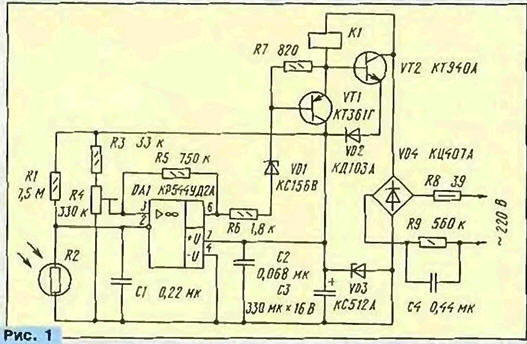
Encyclopedia of radio electronics and electrical engineering / Lighting On the pages of the Radio magazine, descriptions of devices that provide automatic switching on of street lighting with the onset of darkness have repeatedly been placed. In the device offered to the attention of readers this time, the problem of controlling an electromagnetic relay is solved in a very original way. Not without interest and constructive design of the machine. When developing a lighting control device, the task was to simplify its circuit as much as possible while maintaining the accurate performance of all working functions. The schematic diagram of the machine is shown in fig. 1, With sufficient natural light, the resistance of the photoresistor R2 is small and the voltage at the inverting input of the op-amp DA1 is less than at the non-inverting one. The voltage at the output of the op-amp is close to the voltage at the positive terminal of the capacitor C3, and the transistor VT1 is closed. In this state, the current flowing through the turnip winding K1 will open the transistor VT2, which will bypass it. The voltage on the relay winding in this case is 2 ... 4 V, which is not enough for it to operate, and therefore the lighting lamps switched on through its normally closed contacts will not light up.
As the illumination decreases, the resistance of the photoresistor R2 increases and the voltage at the inverting input of the op-amp increases. When it reaches the level set by the tuned resistor R4, the op-amp switches and the voltage at its output becomes close to the voltage at the negative terminal of the capacitor C3. Transistor VT1 opens and enters saturation. As a result, the voltage at the emitter is practically equal to the voltage at the collector, which leads to the closing of the transistor \/T2. Now the supply current will completely flow through the winding of relay K1, it will work and its closed contacts will turn on the lighting lamps. The machine is powered from the AC network through the quenching capacitor C4 and the bridge rectifier VD4. With the transistor VT2 open, the current flowing through this transistor and diode VD2 also passes through the zener diode VD3. The 12 V voltage released on it is used to power the control part of the device. When the transistor VT2 is closed, almost the entire current of the winding of the relay K1 continues to feed this node and only a small part of it passes through the resistor R6 and the OUDA1 output. Resistor R5 eliminates repeated switching on and off of lighting lamps with small changes in illumination in the zone of operation of the machine. Capacitor C1 eliminates network interference and slows down the operation of the machine, which reduces the likelihood of turning off the lamps when the photoresistor is briefly illuminated, for example, by the headlights of passing cars. The zener diode VD1 provides a clear closing of the transistor VT1, and the diode VD2 - the transistor VT2. Resistor RXNUMX does not allow, when adjusting the level of operation of the machine, to exceed the maximum allowable common-mode voltage at the input of the op-amp, above which it will no longer work. All elements of the device are placed on a printed circuit board made of foil fiberglass with a thickness of 2 mm and dimensions of 60x60 mm (Fig. 2). The board is designed to install two K / 4-3 capacitors with a capacity of 17 μF and an operating voltage of 0,22 V as C630. You can also use K73-16, but in any case, the operating voltage of the capacitors must be at least 400 V. Oxide capacitor C3 - imported analogue of K50-35, the rest - KM. Fixed resistor R1 - C1 or CMM, the rest of the MLT indicated in the diagram (Fig. 1) power. Adjusted resistor R4 - SPZ-19a.
RPU-2 with a winding resistance of 4,5 kOhm and an operating voltage of 110 V was used as a relay, having two pairs of normally open and normally closed contacts. The current through each pair can, according to the author, reach 10 A. Capacitor C4 must be selected in such a way that, when transistor VT2 is closed, the nominal voltage on the relay winding is provided. The operability of the device is maintained when the capacitance C4 is within 0,22..0,47 μF. The machine uses a photoresistor FSD - G1. This explains the need for a resistor R1 with high resistance. If you install a photoresistor FSK-G1 or SF2-5. the resistance of the resistor R1 will need to be reduced to about 1 MΩ, and the capacitance of the capacitor C1 will need to be increased to 2,2 microfarads. With the same replacement of the photoresistor, it is permissible to use K1UD140 or K6UD140 as an op-amp DA7. Transistor VT1 - any silicon low-power p-n-p structure (for example, the KT361, KT502 or KT3107 series with any letter indices). Although the voltage on the transistor VT2 does not exceed 110 V during the operation of the machine, at the moment the power is turned on it can increase to the full amplitude voltage of the network, which is about 300 V. For this reason, the allowable collector-emitter voltage of the VT2 transistor must be at least the specified value. This voltage has transistors KT506A (B), KT604A (B, AM, BM), KT605A (B, AM, BM), KT850B, KT854A (B), KT859A, as well as BSIT transistors KP957A (B, V), KP959A { cm. "Radio", 1995, No. 3, p. 42), included in exactly the same way as KT940A. Zener diode VD1 - any small-sized one for a voltage of 4,7 ... 7,5 V, VDZ must have a stabilization voltage of 11 ... .15 mA). These requirements are met, for example, by zener diodes D1G, KS50A, KS2B, KS25G. The KTs30A diode bridge can be replaced by four diodes that can withstand a voltage of at least 814 V. The board is placed inside the protective casing of the relay (Fig. 3). The holes in the base of the relay, intended for fastening its mechanism, should be bored out with a needle file, and the mechanism itself, as far as possible, should be shifted to the side. A block of organic glass is glued to the base of the relay and a board is screwed to it.
The outputs of the relay winding are disconnected from the contact lamellas and soldered to the corresponding pins of the board, which are contacts with a diameter of 1 mm from the 2PM connector. Power conductors (220 V) are connected to the released lamellas. The photoresistor is connected with two twisted wires directly to the board contacts (Fig. 3). The device is preliminarily regulated when powered from a source whose voltage is somewhat less than the stabilization voltage of the zener diode VD1, by connecting it in parallel with this zener diode. The photoresistor should be shaded so that its illumination is close to that at which street lighting is turned on. Now, by connecting a voltmeter to the output of the op-amp DA3 and the negative terminal of the capacitor C4, rotating the trimmer resistor R10, you need to make sure that the voltage at the output of the op-amp changes abruptly somewhere in the middle part of the adjustment range. If this does not happen, a voltmeter with an input resistance of at least 3 MΩ should check the voltage on the photoresistor - it should be close to half of the voltage on the capacitor C1. Otherwise, it must be set to this value by selecting the resistor R1. After that, with a darkened or disconnected photoresistor, you need to apply mains voltage to the machine. In this case, relay KXNUMX should work. Being careful, you can check the voltage on its winding, and if it differs greatly from the nominal value for this type of relay, select the capacitance of capacitor C4. The RPU-2 relay has a special coil that covers part of the core and makes the relay insensitive to supply voltage ripples. When using a different type of relay, it may be necessary to connect a smoothing capacitor with a capacity of about 1 uF in parallel with the winding. The photoresistor must be installed in a place protected from precipitation, and so that the sun's rays and the light of the switched on lamps do not fall on it. To fulfill the first of these conditions, it is recommended to orient the photoresistor to the north, covering it with small screens from the west and east. The final adjustment of the level of operation of the machine is carried out at the installation site by resistor R4, achieving relay operation at threshold illumination. If instead of the photoresistor R2 you turn on the thermistor, then by selecting the resistance of the resistor R1 accordingly, you can get a good thermal stabilizer. Author: S. Biryukov, Moscow
Machine for thinning flowers in gardens
02.05.2024 Advanced Infrared Microscope
02.05.2024 Air trap for insects
01.05.2024
▪ Universal programmer with USB interface ▪ The car should not drive silently ▪ Spy stones scattered across Afghanistan ▪ 2-Port PCIe 3.0 Converged Bus Adapter ▪ Liquid graphene transistor for implantation
▪ section of the site Security and safety. Article selection ▪ article Man is a social animal. Popular expression ▪ article How did the cards get their names? Detailed answer ▪ article plumber. Standard instruction on labor protection ▪ article Riddles about wild animals
Home page | Library | Articles | Website map | Site Reviews
www.diagram.com.ua |


 Leave your comment on this article: