|
|


 Arabic
 Bengali
 Chinese
 English
 French
 German
 Hebrew
 Hindi
Hindi Italian
 Japanese
 Korean
 Malay
Malay Polish
 Portuguese
 Spanish
 Turkish
 Ukrainian
 Vietnamese
|
ENCYCLOPEDIA OF RADIO ELECTRONICS AND ELECTRICAL ENGINEERING Soldering iron digital power controller. Encyclopedia of radio electronics and electrical engineering
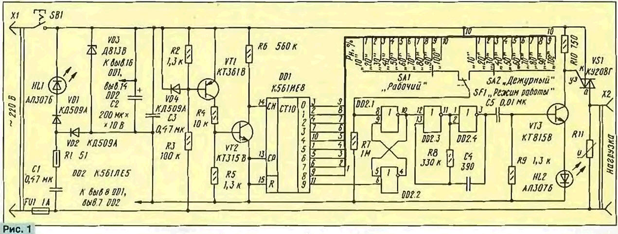
Encyclopedia of radio electronics and electrical engineering / Power regulators, thermometers, heat stabilizers The optimum temperature of the tip of an electric soldering iron is the most important condition for obtaining high-quality soldering. In amateur radio practice, this is of particular importance, since when installing a radio engineering device, the designer has to use the same soldering iron with interchangeable tips that differ significantly in their thermal characteristics. The use of various solders, the brands of which are often unknown, also requires experimental selection of the temperature of the soldering tip. The author of the article analyzes the effectiveness of power regulators, familiar to radio amateurs from publications in our magazine, and offers for repetition his own version of the soldering iron heating temperature regulator - digital. The soldering iron heating control method [1], when its power is regulated only in the non-working state (the soldering iron is on a stand), and in the working power is 100%, gives positive results only with a non-replaceable tip. Amateur radio practice shows that good results can be achieved by separate operational regulation of the soldering iron power in operating and standby modes. This method is even preferable to single-mode fine temperature stabilization of the tip, since it allows you to find a compromise between constantly maintaining the soldering iron in a state of readiness for many hours and wear of the working part of the tip due to the dissolution of copper in the solder. At present, some "amateur radio standard" has been established for medium power regulators for thermal devices [2]. Its essence lies in the fact that the regulation is carried out by the pulse-width method, with the opening of the power trinistor or triac at times close to the transition of the mains voltage through "zero". It is often referred to as the "silent regulation" method. The use of CMOS chips provides a simple circuit solution for generating a pulse-width signal. Its disadvantages include, perhaps, the fuzziness of the generator in the extreme positions of the setting resistor engine and the need to mark the power scale. From these shortcomings, the device [13] is free, in which the digital principle of forming a pulse-width signal is applied. It is especially convenient when forming a multi-mode soldering iron power control, since it does not contain elements that require adjustment when switching modes. A diagram of such a variant of the soldering iron digital power controller is shown in fig. 1. The triac controller described in [4] was used as a basic solution. A NI LED has been added to the power supply of the microcircuits, signaling that the device is connected to the network. This addition turned out to be, as it were, "free * - the LED is powered by a half-wave of mains current that recharges the quenching capacitor C1, which is not used directly to power the device. The average current flowing through the LED" does not exceed 15 mA. When changing the polarity, almost all the reverse voltage, equal in value to the sum of the stabilization voltages of the zener diode VDZ and the direct voltage drop across the VD2 diode, is applied to the VD1 diode, the reverse resistance of which is significantly greater than that of the LED.
If the device is supposed to be operated at an elevated temperature, which increases the reverse current of the VD1 diode, it can be shunted with a 1 ... 3 kOhm resistor to protect the LED from reverse voltage. Transistor VT1 is used to highlight the moment of transition of the mains voltage through "zero". Diode VD4 protects the emitter junction of this transistor from a reverse voltage half-wave. Transistor VT2 inverts the signal taken from the collector of transistor VT1, increases the steepness of the front, which allows it to be fed directly to the CN input of the decimal counter DD1 without any additional drivers. The front of the counting pulse at the input of the microcircuit is formed at the end of each positive (relative to the lower according to the network wire diagram) half-cycle of the mains voltage. At the same time, a "running * high-level signal (log. 0) appears at the outputs 9-1 of the counter, which has a built-in decoder. When a signal of this level occurs at output 9 (pin 11) of the counter, the RS flip-flop assembled on the elements DD2.1 , DD2.2, is set to a high level state at pin 10 of the DD2.1 element, which disables the operation of the triac trigger pulse generator VS1. The generator is made on the elements DD2.3, DD2.4. In this state, the load of the regulator is de-energized. the network will occur after switching the RS-flip-flop to the opposite state by a high-level signal at pin 8 of the DD2.1 element. The moment of arrival of the load on pulse relative to the off pulse is determined by the output number of the counter connected to pin 8 of element DD2.1. Thus, the power supplied to the soldering iron in operating mode and standby mode determines the position of the contacts of the switches SA1 and SA2, respectively. The change of modes occurs with the SF1 switch when its button is pressed with a rocker that holds the soldering iron on the stand. In both modes, the power from 10 to 100% in increments of 10% is set by switches SA1 and SA2. Resistor R7 eliminates the uncertainty of the signal at pin 8 of the element DD2.1 when switching. In the working periods of the network, the triac start pulse generator \/S1 operates continuously, which allows you to turn on the triac with an active load of 60 W at a mains voltage of about 20 V. You can visually assess the relative power delivered to the load by the glow of the HL2 indicator. Although current pulses of the triac control electrode with a value of several tens of milliamps pass through it, the average current is a few milliamps. Since the constant component of the signal at the output of the regulator is close to zero, under certain restrictions it can control the power of low-voltage soldering irons connected to the network through a step-down transformer. The limitations are related to the peculiarity of the transformer operation. If the transformer load is disconnected, a high-quality inductor is connected to the regulator output, on which voltage surges occur that are almost equal to twice the amplitude supply voltage - about 600 V. This mode is highly undesirable, therefore, to ensure the safety of the regulator in case of accidental load switching, the regulator output is shunted by a varistor R11 with a characteristic break point of 350 ... 300 V. But if the regulator is used only with an active load, the varistor can be excluded. The second limitation is associated with transient processes in transformers due to their low operating frequency. When the transformer is connected to the network (even at zero voltage), the first half-cycle is spent on the primary magnetization of the magnetic circuit, accompanied by an increased current of the primary winding. For example, for the popular soldering iron EPSN 25/24 (GOST 7219-83), connected to the network through a transformer, the amplitude of the current pulse was 2,5 A, which is 12 times greater than in the steady state. The value of the current amplitude of the second half-cycle exceeded the steady-state value approximately by 50%, and for the third half-cycle - about 10%. Therefore, it is desirable to turn on even a loaded transformer as infrequently as possible. This is due to the use of an integer number of full periods for power control, which, on the one hand, provides a close-to-zero value of the constant component, and on the other hand, a compromise between the thermal inertia of the load, ease of implementation and a decrease in the number of load switching per unit time. At one time, our industry produced low-voltage soldering irons, powered from the mains through a quenching capacitor built into a plastic case, close in size to a transformer unit of the same power. These soldering irons cannot be connected to the regulator. And if this still happens, the fuse FU1 will protect the regulator from failure. The appearance of the regulator is shown in fig. 2, and the layout and installation of its parts - in fig. 3. Structurally, it is made in the form of a stand for a soldering iron (a plastic case was used from a unified power supply for household radio equipment). Most of the parts are placed and mounted on a universal printed circuit board.
The soldering iron is placed on two metal racks of the stand, bent from steel wire with a diameter of 2,5 mm. The nose strut is movable, its rocker is mechanically connected to the push button switch SF1 (MP1-1). Switch ZV1 (push type from a table lamp), switches SA1, SA2 (MPN-1) and LEDs НL1, HL2 are placed on the top panel of the device. Since the position of the contacts of the switches SA1 and SA2 uniquely determines the power delivered to the load, the HL2 LED is needed only for general monitoring of the device's performance, so it can be excluded if desired. If the acquisition of small-sized multi-position switches is difficult, they are replaced by the female part of a two-row multi-pin connector, using a single pin part as a movable contact, soldering a thin flexible wire to it. To avoid contact with the mains, it is better to use a connector with recessed sockets, and to open the circuit of the movable contact of the switch SF1, include a resistor with a resistance of 91 ... 100 kOhm. The regulator is designed for load power up to 150 W, so the triac can work without a heat sink. To reduce the size and facilitate the layout of the device parts, you can use a miniature triac TC-106 in a plastic case, mounted on an aluminum flag heat sink radiator with a surface area of 10 cm2. Literature
Author: P. Polyansky, Moscow
Artificial leather for touch emulation
15.04.2024 Petgugu Global cat litter
15.04.2024 The attractiveness of caring men
14.04.2024
▪ Do not charge your smartphone at night ▪ What does the neural network see? ▪ New materials will replace genuine leather ▪ Protein found to prevent preterm birth ▪ JMGO Smart Wall O1 Ultra Short Throw Projector
▪ section of the site Children's scientific laboratory. Article selection ▪ article What is memory? Detailed answer ▪ article Knitter knitwear, linen. Standard instruction on labor protection ▪ article solar brazier. Encyclopedia of radio electronics and electrical engineering ▪ article Ash saves the map. Focus secret
Home page | Library | Articles | Website map | Site Reviews
www.diagram.com.ua |


 Leave your comment on this article: