|
|


 Arabic
 Bengali
 Chinese
 English
 French
 German
 Hebrew
 Hindi
Hindi Italian
 Japanese
 Korean
 Malay
Malay Polish
 Portuguese
 Spanish
 Turkish
 Ukrainian
 Vietnamese
|
ENCYCLOPEDIA OF RADIO ELECTRONICS AND ELECTRICAL ENGINEERING IR communication line in burglar alarm. Encyclopedia of radio electronics and electrical engineering
Encyclopedia of radio electronics and electrical engineering / Safety and security When the laying of wire lines is impossible, and the use of radio is difficult for one reason or another, when creating security systems, they often turn to infrared (IR) technology. This article describes an IR transmitter that can be made by a radio amateur who does not have much experience in designing such devices. Large interference in the radio channels allowed in Russia for security systems (26 kHz and 945 kHz), the ease of their blocking, various administrative and financial obstacles that arise when using radio in security alarm devices, force us to look for other means of wireless communication. With the advent of semiconductor emitters capable of generating powerful IR flashes, this possibility has become a reality. On fig. 1 shows a diagram of an IR transmitter. On the elements DD1.1 and DD1.2, a clock generator is assembled, operating at a frequency of 32 Hz. DD768 - a counter, at the output 3 of which there are pulses with a frequency of 11 Hz, and at the output 16 - 14 Hz. Elements DD2-DD2.1 form a switch. At its output (DD2.4), pulses appear with a frequency of 2.4 or 2 Hz, depending on the voltage level at pin 16 of the DD5 element.
In standby mode, the security loop is closed and at pin 5 DD2.1 - low level. A high level from the output of the element DD2.2 allows the passage of pulses with a frequency of 2 Hz through the element DD2.3. The output of DD2.1 is also high, so the pulses follow through the element DD2.4. When the security loop breaks, a high level occurs at pin 5 of DD2.1 and pulses with a frequency of 16 Hz pass through this element. The output of the element DD2.2 is a low level, so the passage of pulses through DD2.3 is prohibited. At the output of DD2.3 - a high level, and pulses with a frequency of 16 Hz pass through the element DD2.4. The P1C1 circuit eliminates the influence of pickups on the security loop. The differentiating circuit P5C3 and the elements DD1.4-DD1.6 form short pulses with a duration of 2.4 μs from the meander coming from the output DD10. The current arising in the collector circuit of the transistor VT1 excites the IR diode BI1, and short IR flashes are emitted into space. So, the transmitter always emits something: either rare impulses, if there are no grounds for alarm, or frequent ones in alarm mode. The most important parameter of the IR transmitter, as well as any element of security equipment, is its efficiency in standby mode. In table. 1 shows the dependence of the current consumed by the transmitter, Icont, on the voltage of the power supply Upit. In the alarm transmission mode, Iload increases by about 10%.
Low power consumption allows you to enter a backup power supply directly into the transmitter housing without increasing its dimensions. These can be, for example, six-volt batteries GP11A, E11A (diameter 10,3 and height 16 mm) or GP476A, KS28, K28L. (13 mm in diameter and 25 mm high), etc. The duration of continuous operation with such a source will be several hundred hours. Shown in table. 1, the dependence of the current through the IR diode Iimp on the supply voltage makes it possible to judge the power of the IR flashes emitted by the transmitter, and, accordingly, its "range". The printed circuit board of the transmitter is made of double-sided foil fiberglass with a thickness of 1,5 mm. On fig. 2a shows the configuration of the conductors, and in fig. 2b shows the placement of parts. The foil on the side of the parts (shown in blue) is used only as a common wire. The places where the leads of resistors, capacitors, etc. are soldered to it are shown in black squares, and the connections of the "grounded" pins of the microcircuits or the positions of the wire jumpers are shown in squares with light dots in the center.
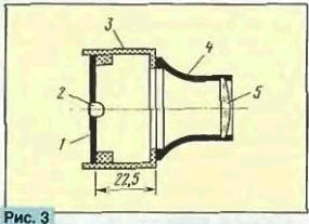
A hole for an IR diode is drilled in the center of the board, its leads are soldered to the corresponding extensions on the printed conductors overlaid. Capacitors C1, C2, C5 - type KM-6 (outputs in one direction), and C3 - KM-5a (outputs in different directions). Electrolytic capacitors C4 and C6 - any type, however, the diameter of the capacitor C6 must be no more than 10 mm. All resistors are MLT-0,125. Commercially available IR diodes are designed to work in remote control devices for household radios and have a fairly wide radiation pattern - up to 25 ... 300. To increase the "range" of such an emitter, it is necessary to use a condenser lens (Fig. 3). Here: 1 - printed circuit board; 2 - IR diode; 3 - transmitter case (high-impact polystyrene 2...2.5 mm thick); 4 - clip of a standard five-time magnifying glass (it should have a "x5" icon on it); 5 - lens. The magnifying glass is glued to the front wall of the case, in which a hole with a diameter of 30 ... 35 mm is made. Glue - pieces of polystyrene dissolved in solvent 647. They also glue the body itself. With the distance between the base of the magnifying glass and the printed circuit board indicated in the drawing, the IR diode is approximately at the focus of the lens and the transmitter radiation is compressed into a narrow beam. This greatly increases the power of the IR signal at the other end of the communication line.
When placing the transmitter, you need to remember a very narrow radiation pattern of its radiation - the attachment point must allow precise aiming of the transmitter and its rigid fixation in the best position. You can use, for example, a swivel head from a camera or movie camera, mounting it on a wall, window frame, etc. And you can perform this node as shown in Fig. 4. The fastening unit consists of a piece of copper wire with a diameter of 1,5..2,5 mm with brass circles soldered at the ends (these can be, for example, old five-kopeck coins). One of them is fixed with screws to the side wall of the emitter (thread - in the wall), the other - to the support. The wire is bent so that the emitter takes the desired position. To avoid significant vibrations, the wire should be shorter.
Tests have shown that with a supply voltage of 6 V, the transmitter is able to provide communication at a distance of 70 m. But this is not the limit. The dependence of the distance r on the current Iimp ceteris paribus has the form: r=KVIimp where K is a coefficient that takes into account "other conditions". Thus, at Upit=10 V r=100 m. The current in the IR diode can be increased by selecting the resistor R7: Iimp=(Upit-4)/R7. But this must be done with caution: in any combination of Upit and R7, the current amplitude in the IR diode should not exceed 2 A in order to avoid damaging it. Unfortunately, the maximum allowable value of the pulsed current in IR diodes has to be established experimentally - as a rule, this information is not available in the reference literature. A significant increase in the power of IR pulses can be achieved by using an AL123A type IR diode and rebuilding the "high-current" part of the amplifier as shown in Fig. 5.
In this case, the current in the pulse Iimp=10 A can be obtained - permissible for an IR diode of the AL123A type. Resistor R4 - homemade, wound from wire with high resistivity. The length of the wire is determined by a digital ohmmeter or in accordance with the table. 2.
The amplitude and shape of the current that excites the IR diode is controlled by connecting the oscilloscope to the resistor R4. The emitting head can be made as a separate unit. The printed circuit board of a powerful amplifier is shown in fig. 6.
All other elements of the IR emitter can enter the electronic part of the security system as a fragment connected to the IR head with a three-wire cable. Schematic diagram of the IR receiver is shown in fig. 7. Chip DA1 converts the current pulses that occur in the BL-1 photodiode under the action of IR flashes into voltage pulses. The single vibrator, made on the elements DD1.1 and DD2.1, expands this pulse to tf1 = 5 ms (tf1 - R2C5). Single vibrator DD1.3, DD2.3 generates a pulse duration tf2= 1.5 s ( tf2 ~ R4C6), allowing unimpeded counting of pulses by counter DD3 only in this time interval. A sound generator is assembled on the elements DD2.5 and DD2.6.
The receiver is activated by the front of the first IR flash. The single vibrator DD1.1, DD2.1, as well as the single vibrator DD1.3, DD2.3 are launched. At the same time, the DD2.2C7R6 circuit generates a pulse at the input R of the DD3 counter (its duration tR = 7 μs, tR - R6C7). setting the counter to zero As soon as the single vibrator DD1.1, DD2.1 has worked, a low level will appear at the output of the element DD1.1 and the first counting pulse will go to the counter DD3. If the photodetector receives pulses that follow with a frequency of 2 Hz (with this frequency, we recall, IR flashes follow in standby mode), then the output 4 of the counter DD3 remains low, since the front of the fourth pulse (it will appear after 0,5x4 = 2 c - at the end of the counting-allowing interval tf2= 1.5 s) DD3 will be returned to the pre-start state (diagram 4 in Fig. 8). The receiver behaves differently if it receives IR pulses with a repetition period of 62,5 ms, i.e. an alarm signal Since four periods of 62,5 ms each is 250 ms, which is much less than the interval tf2 = 1,5, 3 s, then the fourth pulse will transfer the counter DD4 to the state "5" (high level at pin 1.2). The counter in this state will be blocked (due to the low level at the DD1 output), the HL1,25 LED will turn on and the sound generator will emit an intermittent signal. This will continue for approximately 0,25 seconds, after which there will be a XNUMX second pause and the alarm will repeat.
When the connection is interrupted, the receiver behaves differently. If within about 1,5 s the receiver does not detect an IR flash, the capacitor C8 is discharged through the VD6R11DD2.3 circuit. The transistor VT1 enters saturation, the voltage across the resistor R8 rises to the supply voltage, the output DD1.4 is set to a low level, and the sound generator emits a tone signal with a frequency of 1 kHz. With the appearance of the first IR flash, the capacitor C8 will quickly charge through the R10VD5 circuit, the tone signal will stop and the receiver will begin to analyze the incoming signals. The printed circuit board of the receiver (Fig. 9) is made of double-sided foil fiberglass with a thickness of 1,5 mm.
The photo head of the IR receiver (photodiode BL1, microcircuit DA1, etc.), which is highly sensitive to electrical pickups in a wide frequency range, must be shielded. The screen is made of tin, its cutting is shown in fig. 10.
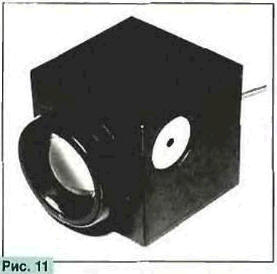
Folds are shown by dashed lines. The bent screen is soldered in the corners and, having installed it in the desired position on the board, soldered to it at two or three points. The appearance of the IR receiver is shown in fig. eleven.
Structurally, the receiver can be made as shown in Fig. 12.
Here: 1 - receiver housing (black polystyrene 2 ... 215 mm thick): 2 - clip of a seven-fold hand magnifier (the handle is cut off); 3 - its lens; 4 - printed circuit board; 5 - photodiode. The holder of the magnifying glass is glued to the front wall of the case, which has a hole with a diameter of about 35 mm (pieces of polystyrene dissolved in 647 solvent). The distance between the photodiode and the lens standing coaxially should be close to the focal length of the lens. This will concentrate the incoming light flux on the photodiode and significantly increase the sensitivity of the photodetector to weak signals. In the case, it is necessary to provide a place for placing the BF1 piezoelectric emitter and the HL1 LED. The same requirements are imposed on the receiver mount as on the transmitter mount: convenient aiming and reliable fixation in the best position must be provided. If, according to the conditions of communication, the IR receiver must be taken out into the street (for communication, for example, with a car parked at the end of the house), then in order to avoid side illumination from extraneous sources that can reduce sensitivity, a lens hood must be pushed onto the objective lens. It can be, for example, a segment of a plastic or metal tube blackened inside, 100 ... 150 mm long, having a suitable inner diameter. In this case, measures must also be taken to protect the entire structure from moisture. Alert devices (piezo emitter, LED) and the power source are, of course, left indoors. But in the "all-weather" version, it is better to make an IR receiver from two parts: an external one, in a waterproof case-hood of which only the lens and a photo head are placed, and an internal one with everything else. These parts are connected with a thin three-wire cable. If necessary, the receiver can be supplemented with an acoustic emitter of higher power, for example, a dynamic head, included as shown in Fig. 13, or piezo siren AST-10 (Fig. 14). The piezo siren retains sufficient power even at a reduced supply voltage (for the radiation of its nominal 110 dB, the supply voltage of this node must be increased to 12 V).
As preliminary tests have shown, the length of the IR communication line with such a receiver and transmitter reaches 70 m. A significant increase in it can be achieved by switching to adjustable optics - if instead of fixed lenses with their approximate focusing, lenses from old cameras with focusing are used. The angle of divergence of rays in the lens of the IR transmitter, its so-called aperture, must be at least 25 ... 300 along the petal of the IR diode, then the lens uses its radiation completely. In the receiver, the diameter of the lens is more important - with its increase, the distance from which you can fix the IR flash of the emitter increases. The "range" of the transmitter can be increased by another 1,5...2 times or more by increasing the brightness of the IR flash. On the other hand, in communication lines not exceeding 20 ... 25 m (a car or a "shell" under the windows of a three-four-story house, a house on the other side of the street, etc.), optics may not be required at all, in any case in the IR receiver. Author: Yu.Vinogradov, Moscow
Machine for thinning flowers in gardens
02.05.2024 Advanced Infrared Microscope
02.05.2024 Air trap for insects
01.05.2024
▪ The robot predicts what the person will say ▪ Solar-powered desalination plant
▪ section of the site Factory technology at home. Article selection ▪ Article Relief of the rib. Tips for a modeler ▪ article What is curling? Detailed answer ▪ Iguazu article. Nature miracle ▪ article Digital frequency converter. Encyclopedia of radio electronics and electrical engineering ▪ article Inverted card. Focus secret
Home page | Library | Articles | Website map | Site Reviews
www.diagram.com.ua |


 Leave your comment on this article: