|
|


 Arabic
 Bengali
 Chinese
 English
 French
 German
 Hebrew
 Hindi
Hindi Italian
 Japanese
 Korean
 Malay
Malay Polish
 Portuguese
 Spanish
 Turkish
 Ukrainian
 Vietnamese
|
ENCYCLOPEDIA OF RADIO ELECTRONICS AND ELECTRICAL ENGINEERING Household metal detector. Encyclopedia of radio electronics and electrical engineering
Encyclopedia of radio electronics and electrical engineering / metal detectors Many people today are looking for treasures, lost coins and jewelry. For such work, of course, you need a good device - a metal detector. The author of the proposed article assembled a similar device, tested it in action and recommends repeating it to everyone. The basis of the metal detector was the device described in the book by Flind E. "Electronic devices for the home" (Energoatomizdat, 1984). During the prototyping and testing of the device, the generator was improved, the element base was replaced with a more accessible one, the output stage of the metal presence indicator was simplified, a pointer indicator was introduced, and a noise filter was installed. The principle of operation of the resulting "transmission - reception" metal detector is to register a signal reflected by a metal object. This signal occurs due to the effect on the metal of an alternating magnetic field of the transmitting (radiating) coil of the metal detector connected to the generator. The receiving coil is located in the same plane as the transmitting one in such a way that the magnetic lines of force passing through it create a small EMF. At the coil terminals, the signal is either absent or very small. A further decrease in the signal is provided by the compensation node. If a metal object enters the field of the coils, the inductive coupling between them changes, an electrical signal appears at the terminals of the receiving coil, which is amplified, rectified, and then filtered. As a result, a constant voltage appears at the output of the filter, which increases as the coils approach a metal object. This signal is fed to one of the inputs of the comparison unit, where it is compared with the reference voltage applied to its second input. The reference voltage level is adjusted in such a way that even a small increase in the signal leads to a significant change in the signal level at the output of the comparison node. This, in turn, activates the electronic key that controls the metal detector buzzer. The scheme of the improved metal detector is shown in fig. 1. The generator, made on the VT2 transistor and the L1C3 circuit, operates at a frequency of approximately 4,6 kHz. The low frequency of the generator provides, on the one hand, a weak response of the metal detector to unwanted signals (for example, those that occur in the presence of wet sand, small pieces of metal, etc.), and on the other hand, good sensitivity. If desired, the generator frequency can be rebuilt by changing the parameters of parts L1, C3 and L2, C6, as well as the R16C11 filter.
The depth of detection of objects depends on the frequency of the working signal, its power, the size of the inductors, as well as the size and shape of the object and its position. The higher the frequency of the generator, the smaller the depth of detection of small objects. The larger the inductors, the greater the depth of detection. For example, this metal detector detects a coin with a diameter of 25 mm at a distance of 13 cm, and an aluminum plate with dimensions of 100x100 mm at a distance of 40 cm. The generator is assembled on a transistor assembly. Transistor VT2 works directly in the generator, aVT1, together with a divider of parts R2-R4, in a thermal stabilizer that provides temperature compensation. The signals arriving at the receiving coil L2 are limited in amplitude (in the presence of a large metal object) by the diodes VD1, VD2, and then amplified by the op-amp DA1.1. The input of this microcircuit receives a compensation signal from the generator through the capacitor C5, resistors R7-R10 and capacitor C8 - it attenuates the signal from the L2 coil arriving at the L1 coil in the absence of metal objects nearby. After amplification, the signal passes through the R16C11 low-pass filter and is rectified by the op-amp DA1.2. With a positive input voltage supplied to the non-inverted input of the microcircuit, the VD3 diode is open and provides negative feedback. Capacitor C12 is charging, the indicator arrow PA1 is deviated. With a negative input voltage, the diode is closed, there is no feedback, and there is zero voltage at the cathode of the diode. The signal from the detector is smoothed by the R21C14R22C15 filter and fed to the DA2.1 comparator, where it is compared with the reference voltage regulated by the variable resistors R23 (rough) and R25 (fine). When the comparator is triggered, the voltage at its output decreases, the transistor VT3 closes, the tone generator assembled on the op-amp DA2.2 starts working. Its output signal is fed to a power amplifier made on a VT4 transistor, the load of which is the headphone BF1 (from a hearing aid). The sound volume within a small range is regulated by a variable resistor R38. The output stage is powered from a separate source, which eliminates the possibility of excitation of the device. The main part of the metal detector is powered by a 12 V source (battery), which is reduced to 3 V using the DA9 stabilizer. The details of the metal detector are mounted on three printed circuit boards (Fig. 2-4) made of one-sided foil fiberglass. They are designed to use resistors MLT-0,125, resistor R10 SP4-1, capacitors C3, C6 - K71-7.
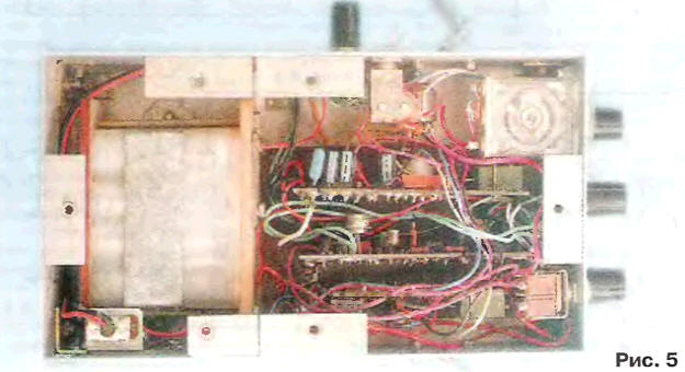
It is permissible to replace the 2TC3103A transistor assembly with the KTC3103, but you will have to change the printed circuit board drawing. Arrow indicator RA1 - recording level indicator from any tape recorder. Boards and other parts of the metal detector are placed in a housing made of insulating material (Fig. 5).
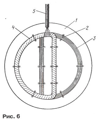
Particular attention should be paid to the manufacture of coils. They are wound on a mandrel with a diameter of 140 mm, which is good to use a glass jar. Each coil consists of 200 turns of enameled copper wire 0,27 mm in diameter with a tap from the middle turn. Before removing the coil from the mandrel, it is tied up in three or four places, and after removal it is wrapped with a strong thread so that the turns fit snugly together. Next, the coils are shaped as shown in Fig. 6, and attach them to a plastic plate 1 with threads 2. The transmitting coil 3 is placed at the bottom, the receiving coil 4 is at the top. The receiving coil must be equipped with an aluminum screen with a gap to prevent the formation of a closed loop. The outputs of the coils are connected to the rest of the device with a cable 5 in a shielded braid. The distance between the vertical (according to the figure) turns of the coils should be equal to 25 mm, it is finally specified after setting the metal detector according to the minimum reading of the PA1 indicator in the absence of a metal object near the coils.
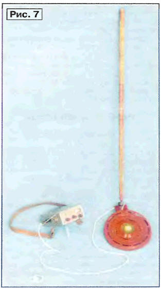
After the final fastening of the coils, they are covered from above with a decorative casing and a rod is attached to it (Fig. 7).
Setting up the metal detector consists in setting the slider of the resistor R10 with the middle position of the slider R8 to such a position that the arrow of the indicator PA1 is at the "zero" mark (for convenience, the arrow is set to the middle mark of the scale by selecting the resistor R19. For this purpose, you may have to change the connection of the terminals of one from the generator coils. During the operation of the metal detector, after its 20-minute establishment of the operating mode, the resistor R8 achieves a "zero" reading of the dial indicator. After that, variable resistors R25 and R23 set the reference voltage close to the operation of the comparator and the appearance of a tonal sound. Naturally, this adjustment is carried out in the absence of metal near the coils. Author: V.Grichko, Krasnodar
Artificial leather for touch emulation
15.04.2024 Petgugu Global cat litter
15.04.2024 The attractiveness of caring men
14.04.2024
▪ Using Water to Recycle Batteries ▪ Microcontrollers PIC18F1220, PIC18F1320 ▪ Gaming monitor ASUS VG249QL3A ▪ New 75V StrongIRFET transistors from IR with ultra-low RDSon
▪ section of the site Microcontrollers. Article selection ▪ article Electric telegraph. History of invention and production ▪ article Where and when did wine come out of the taps instead of water? Detailed answer ▪ statistic article. Job description ▪ article Transceiver Donbass-1M. Encyclopedia of radio electronics and electrical engineering
Home page | Library | Articles | Website map | Site Reviews
www.diagram.com.ua |


 Leave your comment on this article: