|
|


 Arabic
 Bengali
 Chinese
 English
 French
 German
 Hebrew
 Hindi
Hindi Italian
 Japanese
 Korean
 Malay
Malay Polish
 Portuguese
 Spanish
 Turkish
 Ukrainian
 Vietnamese
|
ENCYCLOPEDIA OF RADIO ELECTRONICS AND ELECTRICAL ENGINEERING Electronic label. Encyclopedia of radio electronics and electrical engineering
Encyclopedia of radio electronics and electrical engineering / Safety and security Did someone secretly enter the apartment, taking advantage of the absence of the owners? Was he interested in the contents of the table? Have you looked into the safe? People have always asked these questions. A secret invasion does not always leave visible traces at the scene of the event. But you can make sure that they stay ... The proposed article describes two simple devices that will help with this. On fig. 1 shows a diagram of a kind of electronic label - a device that stores information about some event (for example, whether the door to the apartment was opened in the absence of the owners).
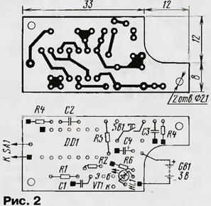
It is based on a trigger assembled on elements DD1.1 and DD1.2. Like any flip-flop, it can be in one of two states: either zero - then the output DD1.1 is low, or single - then the output DD1.1 is high. In which of these states the trigger is located, they find out by pressing the SB1 button: the HL1 LED turns on - there is one in the trigger, it does not turn on - zero. Reading will last while the SB1 button is pressed and for some more time (about 0,5 s). At the end of the front of the signal that closes the transistor VT1, at the output of the element DD1.4, a pulse is formed with a duration of about 0,4 ms, which returns the trigger to its original zero state. The "mark" sensor is a normally open sensor SA1: when its contacts are closed, the trigger goes into a single state. The trigger will work even with extremely high contact resistance, if the closing time is more than 10 ms. In other words, not only a reed switch, a button, a microswitch, etc., but also almost any contact pair can be used as SA1. In choosing its design and placement, it is only necessary to take measures to ensure that contact cannot occur in it by chance, and the insulation resistance of the line connecting it with the device would be at least 10 MΩ. Relatively high requirements for the quality of the line insulation are associated with the value of the resistor R2, which becomes the main energy-consuming element of the device when the sensor is closed for a long time. But if the contact in SA1 is short-term, then the resistance of the resistors R2 and R1 can be significantly reduced (accordingly, the capacitance of the capacitor C1 is also increased). In this case, the requirements for isolation of the communication line will be less stringent. The device is mounted on a printed circuit board (Fig. 2) with dimensions of 45x20 mm, which is made of fiberglass laminated on both sides with a thickness of 1 ... 1.5 mm. The foil under the parts is used only as a common wire (it is not shown in Fig. 2): the connection points with it are shown by black squares. Conclusion 7 of the DD1 chip is pre-bent. In places where conductors pass, protective circles with a diameter of 1,5 ... 2 mm should be etched.
All resistors - MLT-0,125. Capacitors C1-C3 - KM-6 or K10-17b, C4 - K53-30. Holes with a diameter of 2,1 mm are used to fasten the board in the case, which can be glued from sheet high-impact polystyrene 1 ... 1,5 mm thick. Although in some cases the body is not required. The device is powered by a 3-volt lithium cell, for example, a Li 114 cell from SAFT. The power supply is placed in the cutout of the board and soldered to it with short conductors. Li114 - an element with soldered leads. A less reliable, but also frequently used way to ensure long-term contact is the elastic clamping of gilded surfaces. A lithium galvanic cell, which almost does not lose its charge even during very long storage (after 5 years, at least 85% is retained), is best combined with a "tag", the current consumption of which in standby mode is less than 0,5 μA, and in alarm mode indication - 2,5 mA. The 3-volt element can be replaced by two 1,5-volt ones connected in series. If the device is not intended for long-term autonomous operation, for example, silver-zinc STs-21 (or STs-0,038), STs-0,08, STs-32 (or STs-0,12) are suitable. Their electrical capacity is such that they would rather lose their energy supply due to self-discharge than be used up. More information about batteries can be found in the reference book Varlamov R.G., Varlamov V.R. "Small-size current sources", vol. 1129 - M .: Radio and communication, 1988.80s. (MRB). Of course, the power source can be different, ranging from 2 to 12 V. The lower limit of the supply voltage is determined experimentally. Although the guaranteed minimum for K561LA7 microcircuits is 3 V, the device worked reliably even at 2 V. Note that 2 V is the voltage of a 3-volt lithium cell in a discharged state. Standby current remains extremely low even when powered by 12V. A fully assembled device (with or without a case) can be cut into a door, mounted into a wall, into a table, into a bookshelf. You can just leave it among the objects that mask it. It remains only to press the button when leaving, and again - when returning. And if the LED lights up, the secret autopsy most likely took place. And if the other "marks" placed here show the same, the last doubts will disappear ... Obviously, the trigger cue must be outside the controlled space, in any case - its button and LED. However, in some cases, for example, when controlling external doors, this causes certain difficulties. A schematic diagram of an electronic tag, the state of which is assessed not before, but after opening the controlled premises, is shown in Fig. 3.
At the heart of this device is the counter DD2. By pressing the button SB1 "Protection", the counter is transferred to the initial zero state. At a low level at the input of the SR, the counter DD2 responds to signals arriving at its input CN: with each drop from low to high, the contents of the counter increase by one. At a high level at the CP input, the operation of the counter is blocked. Self-locking of the counter will occur after a high level appears at output 3 (pin 7) of the DD2 microcircuit, i.e. after three units enter the counter. A single vibrator is assembled on the elements DD1.1 and DD1.2, which is switched to the active state when the contacts of the SA1 sensor are closed. In this state, no longer reacting to the on/off of the sensor, the single vibrator will stay for 0,7 s. Returning to its original state, the one-shot generates a drop at the input CN DD2, increasing the contents of the counter DD2 by one. The display unit includes an element DD1.4 and a transistor VT1 with an LED HL1 in the collector circuit. Whether the counter DD2 has gone to state "3", find out by pressing the button SB2 "Indication". The printed circuit board for this version of the device is shown in fig. 4. This board is also made of fiberglass with a thickness of 1 ... 1.5 mm foiled on both sides, and the upper side is used as a common wire. The designations in the drawing are similar to the board in fig. 2. A black square with a light dot in the center shows the position of the wire jumper connecting the SB1 button to the common wire.
All resistors - MLT-0,125. Capacitors C1-C3 - KM-6 or K10-17b, C4 - K53-30. To avoid accidentally pressing the SB1 button, it must have a secret drive. The state "3" in the counter DD2 is selected based on the fact that the first unit will be written to the counter by the person leaving the controlled area last (before that, he activates the protection by pressing the SB1 button), the second - by the first to return. There shouldn't be a third... In contrast to the trigger electronic label, here a time limit is imposed on the SA1 contact sensor. For the signal to be recognized as a single one, the contact closure time must be greater than the multivibrator response time (0,7 s). The sensor should work (turn on and off) only at some point in time, for example, immediately before the slamming of the outer door. The interval of insensitivity of the system to chatter (0,7 s) adopted here is usually quite sufficient, but if desired, it can be significantly increased. This can be done by increasing the resistance of the resistor R4 or the capacitance of the capacitor C2. This electronic label, like the trigger one described above, remains operational at a supply voltage of 2 to 12 V. The current consumed by it in standby mode is also small - less than 0,5 μA. Here, too, the best power source is a 3 V lithium battery. With a higher supply voltage, you will need to take into account the current consumed by the device in alarm indication mode (see table).
Author: Yu.Vinogradov, Moscow
Machine for thinning flowers in gardens
02.05.2024 Advanced Infrared Microscope
02.05.2024 Air trap for insects
01.05.2024
▪ DisplayPort support in USB Type-C ▪ Created the highest quality laser ▪ Attitude towards people can be changed
▪ section of the website Electrotechnical materials. Article selection ▪ article English for physicians. Crib ▪ croupier article. Job description
Home page | Library | Articles | Website map | Site Reviews
www.diagram.com.ua |


 Leave your comment on this article: