|
|
ENCYCLOPEDIA OF RADIO ELECTRONICS AND ELECTRICAL ENGINEERING
Electronic ballasts. Electronic ballast that allows you to adjust the brightness of the lamp. Encyclopedia of radio electronics and electrical engineering
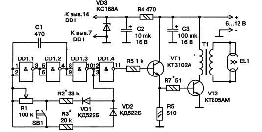
Encyclopedia of radio electronics and electrical engineering / Ballasts for fluorescent lamps This single-ended converter allows adjust lamp brightness and install it in such a way that battery power is used more economically. On fig. 3.78 shows its scheme. The converter consists of a master oscillator and a single-cycle power amplifier. The generator is made on the elements DD1.1-DD1.3. Such a generator allows you to change the duty cycle of the pulses (i.e., the ratio of the pulse repetition period to their duration) with a variable resistor R1, which determines the brightness of the LL. A buffer element DD1.4 is connected to the generator. The signal from DDI.4 is fed to a power amplifier made on transistors VT1, VT2. Amplifier load - LL (ELI), connected through a step-up transformer T1. It is permissible to connect the lamp both with closed filament terminals (shown in the diagram) and with open ones. In other words, the integrity of the filaments of the lamp does not matter.
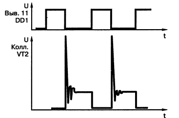
The converter is powered by a DC source with a voltage of 6-12 V, capable of delivering current up to several amperes to the load (depending on the lamp power and the set brightness). Power is supplied to the microcircuit through a parametric stabilizer, in which a ballast resistor R4 and a zener diode VD3 work. With a minimum supply voltage, the stabilizer practically does not work, but this does not affect the operation of the converter. In addition to those indicated in the diagram, it is permissible to use transistors KT3117A, KT630B, KT603B (VT1), KT926A, KT903B (VT2), diodes of the KD503 series (VD1, VD2), Zener diode D814A (VD3). Capacitor C1 - KG, KM, K10-17, the rest - K50-16, K52-1, K53-1. Variable resistor - any design (for example, SP2, SDR), constant - OMLT-OD25. Lamp - power from 6 to 20 watts. The transformer is wound on an armored magnetic core made of 2000NM1 ferrite with an outer diameter of 30 mm. Winding I contains 35 turns of PEV-2 wire with a diameter of 0,45 mm, winding II contains 1000 turns of PEV-2 with a diameter of 0,16 mm. The windings are separated by several layers of varnished fabric. To increase the reliability, the winding II must be divided into several layers, laying a varnished cloth between them. The cups of the magnetic circuit are assembled with a gap of 0,2 mm and tightened with a screw and a nut made of non-magnetic material. With somewhat worse results (the ratio "brightness - current consumption"), a transformer made on a magnetic circuit from a horizontal transformer of the TV will work. Setting up the converter start by checking the master oscillator with the amplifier output stage turned off. An oscilloscope is connected to pin 11 of the microcircuit and the pulses shown in the upper diagram of Fig. 3.79.
Then set the variable resistor slider to the left according to the diagram position "RESISTANCE INTRODUCED". Measure the duration of the pulses and the period of their repetition. By selecting resistor R3, a pulse duration of approximately 20 μs is achieved, and by selecting resistor R2, a repetition period of approximately 50 μs is achieved. After moving the engine from one extreme position to another, they are convinced of the change in the pulse repetition period with their duration unchanged. Next, the output stage is connected, the oscilloscope is connected to the collector of its transistor, and an ammeter with a scale of 2-3 A is included in the power circuit. resistor. Observe the shape of the pulses on the collector of the transistor VT2 - in fig. 3.79 below. This form was obtained when the converter was working with an LB 18 lamp. You may have to select resistors R2, R7 more accurately, and in some cases install a variable resistor of a different value in order to achieve the necessary limits for changing brightness and acceptable current consumption. In the minimum brightness mode, which corresponds to a current of 250-400 mA depending on the supply voltage and lamp power, it is more convenient to start the generator, and therefore turn on the lamp, by pressing the SB1 button. Sometimes it is useful to try to change the polarity of the lamp and check the reliability of its ignition in this mode. Evaluate the efficiency of the converter with different transistors, transformers, mode changes, etc., you can do this. At a distance of about 0,5 m from the lamp, a photodiode or photoresistor is strengthened and an ohmmeter is connected to it. Measure its resistance with a burning lamp and a fixed current consumption of the converter. Next, the part is replaced, the previous current is set with resistor R1 and the resistance of the photocell is measured. If it has decreased, then the brightness of the lamp has increased; the result of the experiment can be considered the best. master oscillator can also be implemented on the widely used timer KR1006VI1 (LM555). On fig. 3.80 shows such a scheme. Here, the timing resistors R2, R3 are variables, as a result of which the pulse parameters and frequency can be changed over a wide range (Fig. 3.30, a), and the connection option shown in Fig. 3.80, b, allows you to change the pulse width of the generator at a constant frequency. The frequency in this case is determined by the formula
The duty cycle adjustment range depends on the ratio of resistors R1, R2.
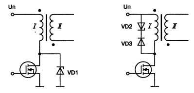
Instead of a power amplifier made on transistors VT1, VT2, R7, R7 (see Fig. 3.78), you can use a field effect transistor KP743, IRF510, BUZ21L, SPP21N10, etc. in the power amplifier (reduce R5 to 100 ohms). Schemes of this option are shown in Fig. 3.81. It will not be superfluous to protect with the help of a special protective zener diode - a suppressor (TRANSIL, TVS, TRISIL) VD1, VD2. Diode VD3 - high-speed with a short recovery time.
Author: Koryakin-Chernyak S.L.
Alcohol content of warm beer
07.05.2024 Major risk factor for gambling addiction
07.05.2024 Traffic noise delays the growth of chicks
06.05.2024
▪ Logitech G CLOUD Gaming Handheld Console ▪ Device for fighting pornography ▪ Garmin Forerunner 620 and 220 Sports Watches ▪ Traffic light for colorblind people
▪ site section Field strength detectors. Article selection ▪ article Take / take on a pencil something. Popular expression ▪ article What was the first mammal? Detailed answer ▪ article Mechanic. Standard instruction on labor protection ▪ article Fittings for shoes. Simple recipes and tips
Comments on the article: Vladimir Thank you so much! The regulator (PWM) on KR1006VI1 (NE555) - works great. I regulate the DC motor 40 A (anchor - down). I left a message for those who follow (well, thanks to the author)! :) [up] [up] Andrei Hello, the frequency formula in this article, according to my calculations, is not true, attach the source from where it was taken. Jury In the diagram, R5-1k is the one on the base of W1 and R5-510 Ohm is the one on the collector of W1. In the description of replacing the amplifier with field workers, there is a small mistake (on transistors VT1, VT2, R7, R7 (see Fig. 3.78) Double R7.
Home page | Library | Articles | Website map | Site Reviews www.diagram.com.ua |


 Arabic
 Bengali
 Chinese
 English
 French
 German
 Hebrew
 Hindi
Hindi Italian
 Japanese
 Korean
 Malay
Malay Polish
 Portuguese
 Spanish
 Turkish
 Ukrainian
 Vietnamese


 Leave your comment on this article: