|
|


 Arabic
 Bengali
 Chinese
 English
 French
 German
 Hebrew
 Hindi
Hindi Italian
 Japanese
 Korean
 Malay
Malay Polish
 Portuguese
 Spanish
 Turkish
 Ukrainian
 Vietnamese
|
ENCYCLOPEDIA OF RADIO ELECTRONICS AND ELECTRICAL ENGINEERING Electronic second hand. Encyclopedia of radio electronics and electrical engineering
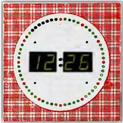
Encyclopedia of radio electronics and electrical engineering / Clocks, timers, relays, load switches The well-known clock circuit, made on K176 series microcircuits, still attracts the attention of radio amateurs by the ease of implementing various improvements: from tick-tock prefixes to correction nodes for the sixth signal of Moscow time. The watch attachment described in this article simulates a second hand using LEDs. The proposed device is designed to refine the electronic clock on the K176 series microcircuits. It is able to turn on the LEDs according to any pre-recorded program. The supply voltage of the clock being modified can be in the range of 8 ... 12 V. The scheme of the device is shown in fig. 1. The memory element in which the program is written is the DS1 ROM chip. The amount of memory of the applied microcircuit is enough to enter four LED control programs into it, which switch depending on the combination of control signals at the address inputs A9 and A10DS1.
A matching stage is assembled on resistors R1 and R2, which lowers the voltage of the logic level coming from the clock to the level of CMOS chips at a supply voltage of 5 V. If the clock is powered from a five-volt source, resistors R1, R2 and regulator DA1 are eliminated by supplying a frequency of 1024 Hz directly to the input of the SR counter DD1. Dynamic indication is implemented on the DD3 decoder and key transistors VT3-VT10. The DD1 counter iterates 8 bytes in turn (8 bits each), i.e. it is possible to connect up to 64 LEDs (the extra 4 bits are simply not used). Switching occurs with great frequency, and the eye does not notice it. The counters DD1 and DD2 are connected in such a way that as a result of dividing every second at pins 5, 6, 11-14 DD2, the binary code is searched from 0 to 63. But since the minute is 60 s, a correction node is introduced on the transistor VT1, which forms short reset pulse at the end of the minute pulse. Thus, the device is synchronized every minute, which is also useful if you press the clock correction button when the second counter of the K176IE18 chip is reset to zero. A node is assembled on the transistor VT2, which switches programs depending on the illumination. If the clock generator is assembled on a K176IE12 chip, this function is not available. All parts of the device, except for the SA1 switch, LEDs and stabilizer, are mounted on a double-sided fiberglass board (Fig. 2).
You can use one-sided fiberglass by replacing the printed conductors with jumpers. Unused microcircuit pins are bitten. The DS1 chip is installed on the socket. The LEDs are mounted on eight arc-shaped boards, seven of which contain eight LEDs each, and the eighth contains only four LEDs (60 LEDs in total). All LED boards are connected with a small-diameter MGTF wire and connected to the main board with two eight-pin TV connectors ONp-VG-8, ONp-VG-25 (not shown in the diagram). It is not at all necessary to place the LEDs in the form of a circle, they can be installed around the perimeter of the watch of any shape. Capacitors C2, C3 and the DA1 chip are located on a separate board, and DA1 is installed on a small heat sink with an area of 30...40 cm2. As a DS1 ROM, you can use any similar chip: K573RF5, 2716, 27c16. The data for flashing the ROM is given in the table.
Any photoresistor can be used in the clock. Instead of KT972A transistors, KT815 with letter indices V-G are suitable. Adjusted resistor R7 - SPZ-38. The device is assembled in a case from the electromechanical watch "Yantar" with dimensions of 24x24x4 cm.
The color of the LEDs can be any, for example, all red (green, yellow) or alternate. It turns out beautifully if every fifth LED is highlighted in a different color. When choosing LEDs, remember that the voltage drop across the red LED is less, i.e. it will glow brighter than green or yellow. It is better to use imported LEDs (especially as green or yellow ones), as they glow well at low current. Of the domestic LEDs, any red ones are suitable - AL307B, etc. So, in the version shown in the photo, AL307KM are used as red LEDs, and imported L93SCG are used as green ones (although it is better to use non-directional ones, since usually the watch hangs above the direct gaze of the beholder). Despite the direct connection of the LEDs to the ROM, the device has sufficient brightness in room lighting. The adjustment of the device consists in the selection of the resistor R2 - the amplitude of the pulses on it should be within 4 ... 5 V. The resistor R7 is selected so that the brightness switching occurs synchronously with the clock. The device draws 200 mA with all LEDs on and 50 mA with one LED on. The current transfer coefficient of the transistor VT2 will change when the temperature changes, so the ratio of the divider R6-input VT2 will also change. To reduce this effect, as R7, you can use a tuning resistor connected according to the potentiometer circuit, and eliminate the resistor R6 by connecting the base of the transistor VT2 directly to the clock photoresistor. The transistor VT2 itself is desirable to use the KT3102 series. Author: A.Plyasov, Ivanovo
Machine for thinning flowers in gardens
02.05.2024 Advanced Infrared Microscope
02.05.2024 Air trap for insects
01.05.2024
▪ Area Ragno GRABBER 2 video capture card ▪ Meizu Smart Button to Control Home Appliances ▪ Found a trace of the impact of the largest meteorite in history ▪ Molecular scissors will remove the AIDS virus
▪ section of the site Spy stuff. Article selection ▪ article by Walter Benjamin. Famous aphorisms ▪ article Can people with Parkinson's who can no longer walk ride a bike? Detailed answer ▪ article Head of the Bureau of Operational Management of the Sales Department. Job description ▪ article Tester for twisted pair. Encyclopedia of radio electronics and electrical engineering ▪ article Encoder of speech messages. Encyclopedia of radio electronics and electrical engineering
Home page | Library | Articles | Website map | Site Reviews
www.diagram.com.ua |


 Leave your comment on this article: