|
|
ENCYCLOPEDIA OF RADIO ELECTRONICS AND ELECTRICAL ENGINEERING capacitive sensor. Encyclopedia of radio electronics and electrical engineering
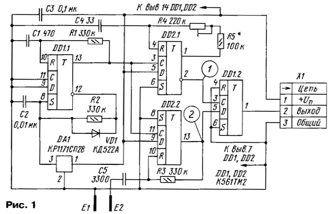
Encyclopedia of radio electronics and electrical engineering / Indicators, detectors The proposed version of the capacitive proximity sensor is economical, operates in a wide range of supply voltage values and has a high stability of the response threshold when the temperature changes. Over the past 20 years, many descriptions of proximity sensor designs have been published in books and magazines for radio amateurs, differing in the principle of operation, sensitivity, complexity, and the element base used. However, many of them are suitable for operation only under conditions close to laboratory ones, at practically constant ambient temperature and supply voltage. For example, the sensor described in [1] is made on a digital microcircuit and is highly economical, but its response threshold depends significantly on the supply voltage. The stability of its operation at high humidity due to the high resistance of the resistor R2 is clearly insufficient and strongly depends on the length of the wires connecting the electronic assembly to the sensing element. The sensors proposed in [2] consume current up to several milliamps, which limits the possibility of their use in self-powered systems. Due to the dependence of the threshold characteristics of the op-amp on the temperature and supply voltage, it is possible that such a sensor will either be constantly in the triggered state or stop working altogether. The proposed sensor is slightly more complicated than those mentioned above, but differs from them in the absence of winding elements, good repeatability, and operates at a supply voltage of 3 ... 15 V, consuming approximately 40 μA (at a voltage of 5 V). It is characterized by the independence of the response threshold from the ambient temperature and supply voltage, low sensitivity to electromagnetic interference and interference. It is possible to accurately calculate the response threshold based on the ratings of the elements used, or calculate these ratings to obtain the required response threshold. The sensor circuit is shown in fig. 1. On the trigger DD1.1, a pulse generator is made. Their duration (approximately 0,2 ms) is set by the R1C1 circuit, and the repetition period (approximately 1,5 ms) by the R2C2 circuit. The undervoltage detector DA1 for some time after turning on the power of the device keeps the voltage at the input S of the trigger DD1.1 at a low logic level, thus excluding the forbidden high level state at both setting inputs (R and S) of the trigger. Otherwise, in the case of an increase in the supply voltage at a rate of less than 2 ... 3 V / ms, the generator will not self-excite.
The generator pulses simultaneously trigger two single vibrators. The first one (on the DD2.1 trigger) generates pulses of exemplary duration, depending on the ratings of the elements R4, R5, C4. The pulse duration of the second single vibrator (on the trigger DD2.2) depends on the resistance of the resistor R3 and the capacitance of the capacitor formed by the metal plates E1 and E2. Isolating capacitor C5 prevents accidental contact with the trigger input DD2.2 DC voltage. The operation of the sensor is based on a comparison of the pulse duration generated by two single vibrators. If the pulse of the second (measuring) single vibrator is shorter than the pulse of the first (exemplary), at the moment of a positive voltage drop at the inverse output of the DD2.1 trigger (at point 1, see Fig. 1), the voltage level at the output of the DD2.2 trigger (at point 2) will be low. Comparison trigger DD1.2, triggered by a positive differential at the input C, will go into a logic low state at the output. Otherwise (the measuring pulse is longer than the reference one), the level at point 2 and at the output of the trigger DD1.2 will be high. When the capacitance between plates E1 and E2 increases with the approach of a foreign object, the low level at pin 2 of connector X1 is replaced by a high one. The threshold value of the capacitance, above which this occurs, is determined by the formula
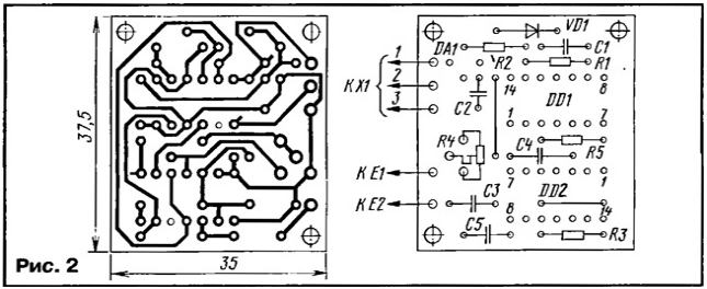
where R4BB is the input resistance of the tuning resistor R4; Svh ≈ 6 pF - input capacitance R of the trigger. With the value of the resistor R5 indicated in the diagram, using R4, you can change the threshold for capacitance from 6 to 32 pF. Since the active elements of the multivibrators are located inside the same DD2 microcircuit, when the temperature or supply voltage changes, their characteristics and the duration of the generated pulses change in the same way. This ensures the stability of the sensor response threshold over a wide range of temperature and supply voltage changes. In the sensor, you can use fixed resistors S2-Z3n, MLT, S2-23 or similar with a power of 0,125 or 0,25 W with a tolerance of at least ± 5%. As R4, it is desirable to use a trimming resistor with a small TKS (for example, SPZ-19a, SPZ-196). For this reason, the widespread use of SDR-38a resistors is not recommended. Capacitors C1 - C4 - any small-sized ceramic (KM-5, KM-6, K10-17 or similar imported ones). The separating capacitor C5 must be high-voltage (for example, K15-5), rated for a voltage of at least 500 V. Its capacitance can be in the range of 1000 ... 4700 pF. Diode VD1 - any of the KD103, KD503, KD521, KD522 series. Chips K561TM2 can be replaced by 564TM2 or their imported counterparts. Undervoltage detector (DA1) should be selected with a threshold voltage that is obviously less than the minimum sensor supply voltage. For example, when powered with a voltage of 5 V, detectors KR1171SP42, KR1171SP47 are suitable, at 9 V - also KR1171SP53, KR1171SP64, KR1171SP73. The electronic unit of the sensor is assembled on a board made of foil fiberglass 1,5 mm thick. A drawing of printed conductors and the location of parts is shown in fig. 2. The sensing element (plates E1 and E2) is recommended to be designed in the form of an "unwrapped" capacitor [2], connecting it to the electronic unit with wires no longer than 50 mm.
Setting up the sensor comes down to setting the threshold with resistors R4 and R5. Operation can be controlled using a circuit of an LED (anode to pin 2 of connector X1) and a resistor with a nominal value of 2,2 ... 4,7 kOhm (between the LED cathode and pin 3 of the connector). Turning on the power, by rotating the engine of the tuning resistor R4, achieve the ignition of the LED, and then turning the engine a little to the right (according to the diagram) - it will go out. The correct adjustment will be indicated by the LED turning on when an object approaches the sensing element. If the LED does not light up even in the extreme left position of the resistor R4 slider, you should install a jumper instead of R5 and repeat the setting. The device can be used as a human touch sensor on plate E2, and any metal object, for example, a doorknob, can play its role. In this case, the E1 plate can be completely abandoned, and the resistors R4 and R5 can be replaced with one resistor with a nominal value of 330 kOhm. One of the variants of the sensor, made by the author, had a sensitive element in the form of a flat capacitor with a plate area of 100 cm2 and a distance between them of 5 mm. It worked confidently when the space between the plates was filled with machine oil by 70% in the temperature range of -30. ..+85 °С. Operations caused by water condensation, approaching hands and other interfering factors have not been recorded. With such a use and application as a sensitive element of a flat or cylindrical capacitor, it is recommended to first estimate the required value of the input resistance of the tuning resistor R4 according to the formula
where Cnp is the capacitance of the connecting wires; Ck is the capacitance of the sensitive element, calculated according to the known formulas for the capacitance of a flat or cylindrical capacitor. If the calculated value turned out to be negative, the resistor R5 should be excluded from the circuit, and if more than 200 kOhm, the value of R5 should be increased so that the resistance R4BB lies within 100 ... 150 kOhm. Finally, the sensor is adjusted in the manner described above. Literature
Author: M. Ershov, Tula
Machine for thinning flowers in gardens
02.05.2024 Advanced Infrared Microscope
02.05.2024 Air trap for insects
01.05.2024
▪ The world's first robot with citizenship ▪ Musical evolution with the help of a computer
▪ section of the site Metal detectors. Article selection ▪ article Sleight of hand, and no fraud. Popular expression ▪ How many legs does a centipede have? Detailed answer ▪ article Crossing by swimming. Tourist tips ▪ Article Miracle cup. Focus Secret
Home page | Library | Articles | Website map | Site Reviews www.diagram.com.ua |


 Arabic
 Bengali
 Chinese
 English
 French
 German
 Hebrew
 Hindi
Hindi Italian
 Japanese
 Korean
 Malay
Malay Polish
 Portuguese
 Spanish
 Turkish
 Ukrainian
 Vietnamese


 Leave your comment on this article: