|
|


 Arabic
 Bengali
 Chinese
 English
 French
 German
 Hebrew
 Hindi
Hindi Italian
 Japanese
 Korean
 Malay
Malay Polish
 Portuguese
 Spanish
 Turkish
 Ukrainian
 Vietnamese
|
ENCYCLOPEDIA OF RADIO ELECTRONICS AND ELECTRICAL ENGINEERING Trip computer for electric bike. Encyclopedia of radio electronics and electrical engineering
Encyclopedia of radio electronics and electrical engineering / Home, household, hobby Readers are invited to a trip computer on the PIC16F876A microcontroller with an external current sensor, designed for an electric bike. On its display, it displays both the parameters of movement and the voltage of the battery, the current consumed from it, power and electricity consumption. The device is made on an accessible element base and is easy to repeat. To control the mode of operation of electric bicycles, various measuring instruments are used. Electrical parameters are measured by power analyzers [1, 2], movement parameters are controlled by various electronic bicycle computers [3] and even mechanical speedometers [4]. There are even special displays for electric bicycles [5], showing all the necessary parameters, but having a high cost. Based on this, I developed a trip computer for an electric bike on a PIC16F876A microcontroller with an external current sensor. Main Specifications
In parentheses, the discreteness of the display of the corresponding parameter is indicated. The trip computer shows the current time with a resolution of 1 minute. The scheme of the trip computer is shown in fig. 1. Microcontroller DD2 (PIC16F876A-I/P) is powered by an oscillator stabilized by a ZQ2 quartz resonator with a frequency of 8 MHz. The XP1 connector is provided for programming the microcontroller. I connected a PICkit2 programmer to it. The microcontroller program was developed in the Flowcode graphical environment [6].
Voltage and current measurements are made using the internal 10-bit ADC of the microcontroller. When measuring voltage, the signal from the voltage divider R5R9R12 is fed to the analog input AN0 (RA0) of the microcontroller. When measuring current, the voltage drop across the current sensor Rш amplifies the operational amplifier OPA241 (DA1). From the output of the op amp, the amplified signal comes to the analog input AN1 (RA1) of the microcontroller. The gain is set by the trimmer resistor R13 in the Oy feedback circuit. Instead of OPA241, almost any single rail-to-rail op-amp in the SO-8 package, for example, OPA340 or TS507, can be used. The program calculates power and electricity consumption based on the measured values of current and voltage. A standard measuring shunt 75SHISV.2-0.5-15 with a voltage drop of 75 mV at a current of 15 A was used as a remote current sensor. Any standard shunt with a resistance of 5 ... 10 mΩ or a similar self-made one can be used as a replacement [7]. The trip computer is powered by a linear voltage regulator formed by a regulating transistor VT1 and a TL431ID (DA2) microcircuit. A VD1R10C6C7 circuit is installed in the power circuit, which reduces the noise generated by a running electric motor. Resistors R16 and R17 ensure even voltage distribution between capacitors C6 and C7. The maximum allowable input voltage (battery voltage) depends on the allowable collector-emitter voltage of the transistor VT1, its allowable power dissipation, the quality of the heat sink and the power released by the resistors R19-R22. With the stabilizer elements indicated in the diagram, the battery voltage should not exceed 75 V. However, the device is able to display values up to 102,3 V on the indicator. The trip computer is made on a single-sided printed circuit board made of fiberglass 1,5 mm thick. A drawing of the printed conductors of the board and the arrangement of elements on it are shown in fig. 2 and fig. 3. In fig. 4 shows its appearance.
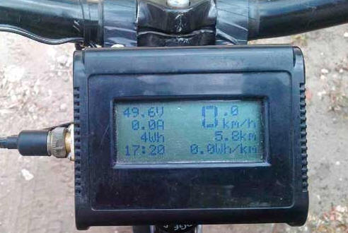
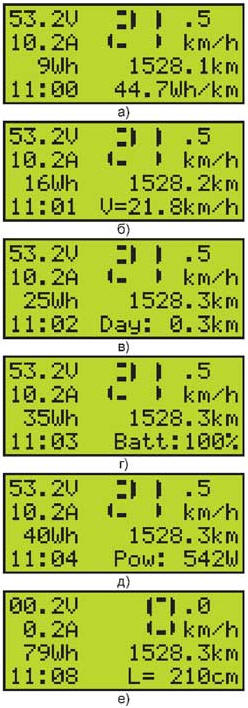
On the front side of the board, a PIC16F876A microcontroller, a ZQ2 quartz resonator, a DS1307 real-time clock chip, trimmer resistors, a VT1 transistor, an XP1 connector (PLS-5R corner pin block) and a PLS-14 block for connecting the HG1 indicator are installed. The mating part of the connector is soldered into the mounting holes of the HG1 indicator - the PBS-14 socket block. A 1V G2032 CR3 lithium battery is installed in the BH-642 holder. All other elements are mounted on the side of printed conductors. A cylindrical quartz resonator ZQ1 (32768 Hz) is soldered into the holes on the side of the printed conductors next to pins 1 and 2 of the DD1 chip. The upper part of its body is soldered to the foil section connected to the common wire. The trip computer board is attached to the LCD board on two metal racks 10 ... 12 mm high using M3 screws. Resistors and capacitors of size 120b for surface mounting are used. Capacitors C6 and C7 are surface-mounted tantalum oxide capacitors in a frame size E. They can be replaced with other capacitors of the same size with a capacity of 6,8 ... A replacement for the npn transistor BD139 in the voltage regulator can be another transistor of the same structure in the TO-126 package with a permissible collector-emitter voltage of more than 80 V, for example, BD179, MJE182 2N5192, BF469, KT817G. A strip of thin sheet of copper or aluminum with an area of approximately 6 cm is placed under the transistor housing.2serving as a heat sink. The transistor is attached to the board with an M3 screw with a nut. To reduce the measurement error shunt Rшshould be located as close as possible to the negative terminal of the battery. All connections to the trip computer can be made with small wires. For connecting to the trip computer reed switch SF1 (path sensor), shunt Rш, and the GB1 battery, a PC7TV connector not shown in the diagram, installed on the trip computer case, was used. The reed switch was taken from a failed electronic cycle computer. Indication of parameters in the trip computer is displayed on a four-line LCD WH1604A with a supply voltage of 5 V without backlight. Its absence is explained by the high current consumed by the backlight (220 mA), which would lead to overheating of the VT1 transistor. The LCD simultaneously displays seven parameters: voltage, current, amount of electricity consumed, current time, speed, total mileage and specific consumption of electrical energy from the moment the trip computer was turned on (see Fig. 4). The speed value is displayed on the screen using pseudographics. This made it possible to bring the height of the digit to two lines, which greatly facilitated reading the speed from the screen. The trip computer is controlled using the buttons SB1 "M" (setting minutes), SB2 "H" (setting hours) and SB3 "P" (indication mode). With successive pressing of the SB3 button in the lower right corner of the screen, instead of the specific consumption of electrical energy (Fig. 5, a), the average speed (Fig. 5, b), daily mileage (Fig. 5, c), battery charge (Fig. 5, d) or the power consumed by the electric motor (Fig. 5, e).
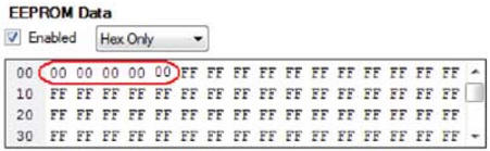
When the SB3 button is pressed for more than 5 s, the program enters the wheel circumference setting mode (Fig. 5, f). With further holding of this button, the circumference of the wheel changes in 1 cm steps from 201 to 215 cm (26-inch wheel). When the device is initially turned on, the wheel circumference is set to 210 cm. 5 s after the SB3 button is released, the wheel circumference setting mode is exited with the set value written to the EEPROM of the microcontroller. When programming the microcontroller, it is necessary to write zeros to the first five EEPROM cells (Fig. 6) to set the initial value of the distance traveled to zero. If this is not done, the mileage will be 1525,7 km.
The program saves the distance traveled in the EEPROM of the microcontroller 3 s after the electric bike stops. To indicate the moment of recording, an asterisk symbol appears for 0,3 s in the upper right corner of the LCD. When the power is turned off, the program resets the values of the unit costs of electrical energy, average speed and daily mileage. To set up the device, instead of a battery, you can use a laboratory power source with an output voltage of 25 ... 50 V and a permissible load current of at least 5 A. As a load equivalent, you can use a powerful wire resistor with a resistance of 5 ... 10 Ohm. Set up the device in the following order. First calibrate its voltmeter. To do this, voltage is applied to the device from a battery or from a laboratory power source, controlling it with an accurate digital voltmeter. By changing the resistance of the tuning resistor R9, the same readings of the exemplary voltmeter and the device being adjusted are achieved. Then the current meter is calibrated. An accurate digital ammeter is connected in series with the load. By applying the supply voltage, by changing the resistance of the tuning resistor R13, the same readings of the exemplary ammeter and the device being adjusted are achieved. If necessary, by selecting the resistor R25, the optimal image contrast on the indicator is set. The trip computer can be installed in any suitable plastic or metal case. Trip computer circuit board file in Sprint Layout 5.0 format and microcontroller program: ftp://ftp.radio.ru/pub/2016/05/tripcomp.zip. Literature
Author: A. Nefediev
Machine for thinning flowers in gardens
02.05.2024 Advanced Infrared Microscope
02.05.2024 Air trap for insects
01.05.2024
▪ Cooked rice is dangerous to health ▪ SONY camcorders burn DVD on the fly
▪ section of the site Normative documentation on labor protection. Article selection ▪ article The third is not given. Popular expression ▪ Chemerits article. Legends, cultivation, methods of application
Home page | Library | Articles | Website map | Site Reviews
www.diagram.com.ua |


 Leave your comment on this article: