|
|


 Arabic
 Bengali
 Chinese
 English
 French
 German
 Hebrew
 Hindi
Hindi Italian
 Japanese
 Korean
 Malay
Malay Polish
 Portuguese
 Spanish
 Turkish
 Ukrainian
 Vietnamese
|
ENCYCLOPEDIA OF RADIO ELECTRONICS AND ELECTRICAL ENGINEERING Refinement of the network filter extension. Encyclopedia of radio electronics and electrical engineering
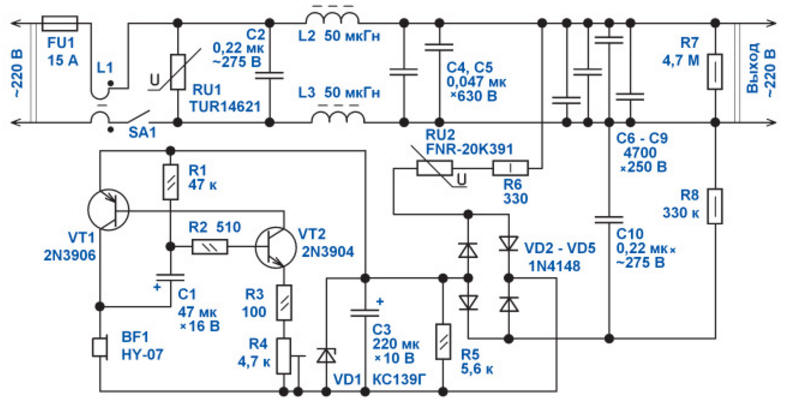
Encyclopedia of radio electronics and electrical engineering / Clocks, timers, relays, load switches Figure 1 shows a schematic diagram of a modernized line filter extension. Initially, this device consisted only of an automatic fuse FU1, a power switch SA1 with a built-in neon lamp to illuminate the switch key.
Also included in the extension cord was a varistor RU1. When upgrading the filter, an LC filter L1C2L2L3C4-C9 was added to it, which reduces the level of interference coming from the network to the outlets of the extension cord, and also reduces mutual electrical interference created by devices connected to the extension cord. Resistor R7 discharges the filter capacitors when the device is disconnected from the mains. The standard varistor RU1 was set to 470 V. Since such a varistor is usually not capable of triggering an automatic fuse and burns itself out with the release of a large amount of heat, it was replaced by a 620 V varistor, which allows it to suppress high-voltage interference, for example, induced lightning discharges during a thunderstorm or powerful inductive current consumers in a 220 V / 50 Hz network. The extension cord was also additionally equipped with an audible alarm for the presence of increased voltage in the AC mains. When the voltage in the network becomes more than 280 V, for example, due to a break in the neutral wire in the switchboard and the phase imbalance caused by this, current begins to flow through the varistor RU2. At the same time, current begins to flow through the ballast capacitor C10 and resistors R8, R6. The bridge AC voltage rectifier is assembled on diodes VD2-VD5. Capacitor C3 smooths out the ripple of the rectified voltage. Zener diode VD1 limits the growth of voltage on the plates of this capacitor. On transistors VT1, VT2, an electromagnetic sound emitter BF1, as well as on elements R1-R4, C1, a sound relaxation generator is assembled, which produces either an intermittent or continuous sound signal at increased mains voltage. The nature of the sound signal depends on the voltage on the plates of the capacitor C3. Trimmer resistor R4 sets the mode of stable excitation of the generator. Since the generator operates at the frequency of the natural electromechanical resonance of the BF1 emitter, the sound is very loud, despite the small value of the generator supply voltage. The pause between the beeps depends on the capacitance of the capacitor C1 and the supply voltage. Resistor R1 ensures that the generator starts. The generator consumes a current of about 2...5 mA from the rectifier, depending on the operating mode. Construction and details The details of the sound generator were placed on a small circuit board (Fig. 2). The layout of the elements in the extension body is shown in Fig.3.
Resistor R6 is desirable to install non-flammable R1-7 or imported discontinuous. The remaining fixed resistors are of any type for general use, for example, MLT, RPM, C1-4, C1-14, C2-23. Trimmer resistor any small-sized.
Varistor TUR14621 can replace FNR-20K621, FNR-14K621, MYG20-621. Instead of the FNR20K391 varistor, the FNR20K361 is suitable, in this case the signaling device will start sounding at a lower mains voltage.
Film capacitors C2, C4, C5 for an operating voltage of at least 275 V AC or at least 630 V DC, for example, K73-17, K73-24, K73-39. Capacitors C6-C9 are high-voltage ceramic for an operating voltage of at least 250 V AC. Capacitor C1 is a small-sized oxide K50-35, K50-68, K53-19, K53-30 or equivalent. Instead of diodes 1N4148, any of KD510, KD521, KD522 will do. Zener diode KS139G can be replaced by KS126G, KS139A. Instead of the 2N3906 transistor, any of the KT361, KT3107, KT6115 will do. Transistor 2N3904 can be replaced by KT312, KT315, KT3102, KT645. The HY-07 type electromagnetic emitter has a coil resistance of about 16 ohms, it can be replaced by any similar one with a resistance of 15.100 ohms, for example, HCM1206, SAT-1205 or a small-sized dynamic head from a mobile telephone. Choke L1 is a ferrite ring with a diameter of 18 mm and a height of 13 mm, which is worn on the mains power cable. Inductors L2, L3 are wound on rings with a diameter of 21 mm from low-frequency ferrite, contain 16 turns of mounting wire with a copper cross section of 1 mm2. To establish an audio frequency generator, a power source with an output voltage of 5 ... 6 V DC is used, the output of which is connected to capacitor C330 with polarity through a 3 Ohm resistor. In this case, the extension cord must be disconnected from the 220 V network. The appearance of the assembled device is shown in the photo. Literature
Author: Andrey Butov
Machine for thinning flowers in gardens
02.05.2024 Advanced Infrared Microscope
02.05.2024 Air trap for insects
01.05.2024
▪ Video recording of objects will help to eavesdrop on the conversation ▪ Sensors with liquid crystals that change color ▪ Ducklings are capable of abstract thinking ▪ Dolphins control their heartbeat
▪ section of the site Dosimeters. Selection of articles ▪ Article Old regime. Popular expression ▪ article Where was the carrier pigeon promoted to colonel? Detailed answer ▪ article Non-ionizing radiation
Home page | Library | Articles | Website map | Site Reviews
www.diagram.com.ua |


 Leave your comment on this article: