|
|


 Arabic
 Bengali
 Chinese
 English
 French
 German
 Hebrew
 Hindi
Hindi Italian
 Japanese
 Korean
 Malay
Malay Polish
 Portuguese
 Spanish
 Turkish
 Ukrainian
 Vietnamese
|
ENCYCLOPEDIA OF RADIO ELECTRONICS AND ELECTRICAL ENGINEERING Car security system with satellite tracking of coordinates and transmission of notifications via GSM channel. Encyclopedia of radio electronics and electrical engineering
Encyclopedia of radio electronics and electrical engineering / Safety and security The appearance on the market of relatively inexpensive modules for building GSM modems and signal receivers for satellite navigation systems GLONASS and GPS allows you to create relatively simple and at the same time with good quality indicators designs that can accurately determine the current coordinates of an object, such as a car, and transmit them through channels cellular communication. The proposed device uses ready-made modules with a rich set of functions and a design that allows mounting with a conventional soldering iron. Although the system was designed for use in a car, by modifying the programs of the microcontrollers in it, it is easy to adapt it to other applications, such as tracking large pets. The set of security functions provided for in it is easy to change without connecting the appropriate sensors and removing from the tracker elements that are not required for their maintenance. It is not required to make any changes to the microcontroller program. By simplifying the lighthouse in this way, it can be used, for example, in order to constantly know where a child who has gone for a walk is. The computer, to which the base unit of the system is connected via Bluetooth, indicates the position of the object on the maps of the Google Earth program or the freely distributed SASPlanet program. It is also possible to output information about the position of an object to a cell phone in which a navigation program is installed, for example, Navitel 3.5.0. In principle, the position of an object can be monitored using any device with a navigation program that has Bluetooth. The system consists of two blocks: the actual beacon installed on the controlled object, and the base block. The latter is the leader in all modes, and the beacon is the slave. Executing the master's commands, he determines the coordinates of the object from the signals of the navigation satellites of the GLONASS and GPS systems and transmits them via the GSM channel. In armed mode, the beacon sends voice messages about alarm situations via the same channel. The telephone numbers to which commands are sent and information is transmitted must be pre-recorded in the SIM cards installed in the GSM modems of the beacon and the base unit. The main mode of the base unit is to receive coordinates from the beacon and then transfer them via Bluetooth to a computer or other device that displays them on the map. Voice messages can also be received by a regular cell phone. In the base unit and in the phone, you can use both different SIM-cards, and the same one. To receive GLONASS/GPS signals, the beacon is equipped with an active antenna. With it, the coordinates of a car equipped with a beacon are determined even when it is in the garage. If this is not required, a passive antenna can also be used. This will require minimal modification of the GLONASS / GSM receiver - removal of the choke from it, through which power is supplied to the active antenna. The beacon provides identification of the number from which the incoming call was made, which excludes the possibility of access by unauthorized persons to the system. Since all numbers are stored in SIM cards, they can be changed without interfering with microcontroller programs. If the cellular operator provides for the ability to respond with an SMS message to a USDC request about the status of the subscriber's account of the SIM card installed in the tracker, then the tracker generates such a request by a command sent to it from the cell phone. It sends the information received in response in the form of an SMS message to the sender of the command. The status of the subscriber account of the base unit can be checked using a computer with a terminal program running on it and connected to the base unit via Bluetooth. For this, the block has a special mode of operation. If checking the account status against USDC requests is not possible, then to perform this check, the SIM cards will have to be temporarily moved from the beacon or base unit to the cell phone. The beacon and the base unit are powered by batteries for cell phones, consuming a small current in standby mode. The base unit provides an indication of the battery status. Charge it with a cell phone charger, while charging indication is provided. The beacon's battery is charged from the car's on-board network, but it can also be charged from the same charger as the battery of the base unit. Setting up the system comes down mainly to writing several parameters into the GSM modems of the units and reprogramming the GLONASS/GPS beacon receiver to the required transmission rate of the received navigation information. This is done using a computer through the serial communication ports that the modems and receiver are equipped with. It is also necessary to record voice messages intended for transmission by the beacon into the voice recording and playback chip and program the microcontrollers of the beacon and the base unit. Scheme and design of a GSM modem Consideration of the schemes and design of nodes and blocks of the system, let's start with a GSM modem, which is used both in the beacon and in the base unit. The modem scheme is shown in fig. 1. When working with the SIM900D (U1) module that forms the basis of the modem, it is necessary to follow a few simple requirements in accordance with its operation manual: - before the appearance of a high voltage level at the STATUS output (pin 5), the presence of voltage at the module inputs must not be allowed. This provides a node on transistors VT4 and VT2.2; - the voltage at the module inputs must not exceed 2,8 V. This is provided by a parallel voltage regulator DA1, transistor VT2.1, diodes VD1, VD5; - turn off and turn on the module by connecting the PWRKEY input (pin 12) of the module to the common wire for more than 1 s, which makes the transistor VT1. However, following this recommendation, the manual describes the operation of the module when the supply voltage drops. When the voltage is less than 3,2V, it will automatically turn off. To prevent damage to the module when the battery is abruptly disconnected by an external switch, capacitors C3 and C4 in its power circuit have a total capacitance of 300 μF. The charge accumulated in them is sufficient for the module to correctly perform the shutdown procedure; - an ionistor must be connected to the VRTC input (pin 15) (the ones found in old cell phones were used); - the terminals for connecting the SIM card do not have built-in protection, therefore, it is necessary to install external zener diodes for a voltage of 5 V or protective diodes. In this case, these are diodes VD2-VD4, VD6-VD8.
Jumper S1 is used to select the connection option for an external LED - an indicator of the module operation mode. When it is in position 1-2, the LED cathode is connected to the "Modem" output, and its anode is connected to the power plus. In this case, the transistor VT6 and resistors R18-R20 are not used and there is no need to install them on the modem board. This LED connection is used in the base unit. In the version for the beacon, the jumper is set to position 2-3, the anode of the LED is connected to the "Modem" output, and the cathode is connected to the common wire. The logic of the indicator is the same in both cases. The SB1 button is designed to manually turn the modem on and off. To perform any of these operations, you must press it for 1 ... 2 s, controlling the process of switching off or on according to the state of the LED connected to the "Modem" line. The drawing of printed conductors of the modem board is shown in fig. 2, and the location of parts on it - in Fig. 3. Insert and solder pieces of tinned wire on both sides into the vias, which are shown as filled.
Jumper S1 is formed by connecting a printed conductor going to the top output of the resistor R23 according to the drawing with the collector of the transistor VT5 (position 1-2) or the transistor VT6 (position 2-3). Before installing the SIM900D module on the printed circuit board, it is advisable to apply a little solder paste to the contact pads intended for it (I use BST-506) and heat the paste with a hairdryer until the pads are serviced. This simple preparation will greatly facilitate soldering. If this is not possible, you can solder in the usual way - with a soldering iron with a thin tip. Before soldering on the side contacts of the SIM900D module, you need to apply a drop of flux with a needle (I use F-2000), without it it is difficult to solder these contacts. Resistors R15 and R17 - C1-4-0,125 W, the rest - P1-12 size 1206. Oxide capacitors - TECAP, ceramic - GRM32 X7R. The device is not critical to the choice of element values, with the exception of resistors R14, R15, R17 in the 2,8 V voltage stabilization unit. Almost any resistors and capacitors can be used that are suitable in size. The same applies to bipolar transistors. The necessary oxide capacitors can be found in old mobile phones, there are also ionistors and diodes with a Schottky barrier BAT20J. These diodes can be replaced by others with a low forward voltage drop. Germanium diodes D2B and the like work well. The IRF7343 FET assembly can be replaced with two separate FETs of the appropriate channel type. The only requirement for them is that the threshold voltage must be within 1,5 ... 2 V. Button SB1 - power switch from the mobile phone "Nokia". It is advisable to install the SIM card holder 5190006-008-R exactly like this, otherwise you will have to redo the board. The AP22B antenna is connected to the SIM900D module with an ADA-000-115 adapter cable. Here you can use another type of antenna designed for cellular communications. Scheme and design of the base unit The basic block diagram is shown in fig. 4. It works according to the program stored in the memory of the microcontroller DD1. Pressing the SB1 button in standby mode connects the RXD and TXD lines of the GSM modem to the corresponding lines of the Bluetooth U1 module. As a result, the modem can be controlled from a terminal program running on a computer connected to the base unit via Bluetooth. When the base unit is in the mode of transmitting information from the beacon to the computer, the same button is used to exit the mode without turning off the GLONASS/GPS signal receiver in the beacon.
When you press the SB2 button in standby mode, you enter the information transfer mode, in which this button is used to exit the mode with the GLONASS / GPS receiver turned off. By pressing the SB3 button, they answer an incoming call and request that the beacon transmit information about the current state of the object. It also serves to hang up after a communication session. Please note that the program of the DD1 microcontroller does not detect a release from the beacon, so it must be given manually at the end of the communication session. Otherwise, the GSM modem will terminate the connection, and the DD1 microcontroller may remain in an indeterminate state. Each pressing of the buttons is accompanied by a sound signal emitter HA1. It must be borne in mind that in order to save the energy of the G1 battery in standby mode, the DD1 microcontroller is in the "sleep" state most of the time, "waking up" every 2 s to poll the buttons and control the battery voltage. If you press a button while the microcontroller is "sleeping" or performing a task that is not related to polling the buttons, the command may be skipped. Therefore, the pressed button must be held until a confirmation sound signal is received and only then released. SA1 - unit power switch. By closing the SA2 switch, the system is switched to armed mode, which ensures, in particular, the receipt of voice messages from the beacon. In addition, with the help of transistor VT2 and sound emitter HA1, a call signal will sound in case of an alarm situation. The SA3 switch turns on the U1 module to check its operability, debugging the connection with the terminal device (computer). Dynamic head BA1 serves to listen to voice messages from the beacon. The sound emitter HA1 gives signals of pressing buttons, informs about incoming calls. When the battery G1 is discharged to 1% of its capacity, the HL80 LED flashes briefly, when it is discharged to 40%, the HA1 emitter beeps. While the battery is being charged, the HL1 LED flashes for a short time, after it it lights up continuously until the charger is disconnected from the XS1 connector or from the mains. In accordance with the instructions for the SIM900D module used in the GSM modem, the G1 battery must be lithium-ion. According to information found on the Internet, it is optimal to store such a battery discharged to no more than 70% of its capacity. Based on this, the display modes are selected. The HL2 LED turns on, confirming the establishment of a connection in the data transfer mode and in the modem control mode via the Bluetooth module. The HL3 LED indicates the state of the modem's connection to the cellular network, and HL4 indicates the state of the Bluetooth module. The 74HC4052D multiplexer (DD2) switches the modem's RXD and TXD lines in the required direction depending on the status of inputs A and B: A=0, B=0 - the modem is connected to the microcontroller DD1, which controls it; A=1, B=0 - information received by the modem is sent to the Bluetooth module. A=0, B=1 - the modem is controlled by the Bluetooth module (this is mainly a debugging mode, it is also needed to receive USSD data). In this mode, it is convenient to work directly with the GSM modem from any terminal program running on the computer, I prefer the COM Port Toolkit 3.9 program. Briefly about the HC-07 module. In the simplest case, it is a Bluetooth-RS-232 bridge - in fact, a COM port radio extender. Everything is very simple and easy to integrate into systems operating via the RS-232 interface. On sale you can find many similar modules under the names HC-04, HC-05, BC04, BC05, BC06, RF-BT0417C, BT0417 and a number of others. All of them are based on the BC417143B controller. This solution is called BlueCore4, all modules based on it comply with the Bluetooth 2.0 protocol and even look very similar. Their dimensions are 27x13 mm, they are powered by a voltage of 3,3 V, they consume current up to 30 mA during the connection establishment, which decreases to 12 mA with a stable connection. The speed of the serial port built into them is set by AT commands from the standard range of 1200-115200 Baud (by default - 9600 Baud, eight data bits without parity and one stop bit). In bridge mode, the HC-07 module cannot be a connection initiator (master), but can only be a slave. Since the information transfer rate in the cellular communication channel is 9600 baud, there is no need to change any module settings. The indicator of its operation mode (HL4 LED) in the absence of communication via the radio channel often flashes, and when the connection is established, it glows continuously. There are two printed circuit boards in the base unit - the main board and the GSM modem board discussed above. Printed conductors on the main board of the unit are shown in fig. 5, and the location of parts on it - in Fig. 6. Transition holes into which you need to insert and solder pieces of bare wire or leads of parts on both sides are shown filled.
The element base is the same as in the modem. The microcontroller DD1 is installed in the panel for easy programming and adjustment. The conclusions of the resistors R1, R3, R8 (C1-4-0,125 W) are soldered directly to the pads without drilling holes in the board. Dynamic head BA1 - from the mobile phone "Nokia-3410", but there may be another one with a voice coil resistance of 32 ohms. It is installed directly on the block body. Buttons SB1-SB3 - TS-A1PS-130. Switches SA2 and SA3 - paired DIP-switch VDM1-2. Sound emitter HA1 - without built-in generator, such can be found in old mobile phones, printer boards, etc. The block is assembled in a plastic case measuring 165x65x20 mm. The board is installed in the block case so that the buttons and LEDs are on the front side of the case. A view of the installation of the unit with the bottom cover removed is shown in fig. 7.
Switch SA1 must be designed for a current of at least 2 A (sliding switch KVV70-2P2W is used). It is installed directly on the block body. The XS1 connector for connecting a charger from a mobile phone is also installed on the case. Battery G1 - BP-6M with dimensions 40x40 mm from "Nokia" cell phone. The charger for it must have a stabilized output voltage of not more than 6 V. Scheme and design of the lighthouse The beacon has a GSM modem, which is completely identical to the one used in the base unit. We will not re-examine its scheme and design, but we will consider other nodes assembled on separate printed circuit boards before moving on to the full scheme and design of the lighthouse. The scheme of the GLONASS/GPS receiver is shown in fig. 8. It is assembled on the basis of the SIM68V (U1) module, capable of receiving and processing signals from both satellite navigation systems. The composition of the navigation data output by the module to the serial port corresponds to the NMEA-0183 protocol, described, for example, in the article by V. Vashchenko "Car GSM signaling device with position determination" ("Radio", 2009, No. 8, pp. 28, 29; No. 9 , pp. 41-43). In this case, only $GPRMC messages are used, which carry basic information about the object's coordinates.
The cold start of the receiver when using an active antenna takes about 15 s. This is less than required to connect the beacon to the base unit via the GSM channel. The current drawn from the 3,3 V voltage source does not exceed 100 mA. The voltage of 2,8 V, intended to power the active antenna, is generated inside the module. If such an antenna is not intended to be used, the inductor L1 must be excluded. The node on the transistor VT1 and the LED HL1 are designed to signal the operation of the receiver. When it works, the LED flashes briefly in time with the second timestamps generated by the receiver. The circuit board of the GLONASS/GPS receiver is shown in fig. 9. All elements installed on it are for surface mounting.
On fig. 10 shows the diagram of the charger. It is a pulse voltage stabilizer that lowers the voltage of the car's on-board network to 5 V. It is this voltage that is needed for the battery charging unit in the beacon's GSM modem, which supplies the modem itself and other beacon units.
The printed circuit board of the charger is shown in fig. 11. Oxide capacitors C1, C2 - any type, suitable in size. The magnetic circuit of the inductor L1 is a ferrite ring measuring 12x6x6 mm, taken from an old computer power supply. 20-30 turns of insulated wire with a diameter of 0,7 ... 0,8 mm are wound on it. You can also use a large ring, for example, 17x10x8 mm. But the number of turns of the winding must be changed so that the inductance of the inductor remains equal to that indicated in the diagram.
During the operation of the base unit, it was found that the node of the SIM900D module installed in the modem, which controls the battery charging, sometimes (once or twice a month) "freezes". To eliminate this phenomenon, we can recommend replacing the LM2575S-5.0 chip in the charger with an LM2575S-ADJ with the ability to adjust the output voltage. Having set the output voltage of the charger to 4,1...4,2 V, its output should be connected directly to the unit's battery, thus excluding any charging control from the SIM900D module. Such a refinement will also allow the use of a single-pole power switch for the base unit. The complete diagram of the lighthouse is shown in fig. 12. All main functions are performed by the PIC16F726-E / SP (DD1) microcontroller according to the program recorded in it. It receives commands from a GSM modem and navigation information from a GLONASS/GSM receiver, generates messages for transmission over a cellular communication channel, including voice messages using the ISD5116ED (DD3) speech recording and playback chip.
Selector-multiplexer DD2 switches the serial ports of the microcontroller, modem and Bluetooth module, depending on the direction of information transfer between them. The integrated stabilizer DA3 provides a voltage of 3,3 V to the GLONASS / GPS A3 receiver and the DD3 voice recording and playback chip. When using the beacon as a security device, its XP1 connector is connected to the circuits of the protected object (car) according to the diagram shown in fig. 13. Here SA1 is a security switch hidden in a secret place (for example, in the "torpedo" of a car). The HA1 siren is placed under the hood, and the HL1 LED is placed in a convenient place for observation in the cabin. The LED will show the state of connection of the beacon's GSM modem with the cellular network. Jumper S1 in the modem in this case must be set to position 2-3 (in contrast to its position in the base unit modem).
If the siren is not used, then the transistor VT1 and resistors R15, R17 can not be installed in the beacon. If you refuse to control the ignition on, the elements R9, C5, VD2 are not required, but pin 9 of the DD1 microcontroller must be connected to a common wire through a 1 kΩ resistor. The R6R16C3 circuit generates a signal for triggering a motion sensor installed in the car (I used a Pyronyx ColtX8 sensor). If the sensor is not used, this circuit must be excluded, and pin 11 of the microcontroller should be connected to a common wire through a 1 kΩ resistor. Elements R3, R12, R18, C4 are designed to control the voltage of the car battery supplied to pin 5 of the XP1 connector. The trimmer resistor R18 sets the voltage at pin 4 of the DD1 microcontroller to 1,05 V at the minimum allowable battery voltage (I have 11,2 V). If car battery monitoring is not needed, this circuit can be used to monitor G1 battery voltage in the beacon itself. To do this, disconnect the left output of the resistor R3 from the contact of the XP1 connector and the input of the charger A2 and connect it to the +4,2 V circuit. Reduce the value of this resistor to 7,5 kOhm, and increase the value of the resistor R12 to 10 kOhm. To pin 8 of the XP1 connector in the beacon, a signal generator for the standard car alarm is connected, consisting of a transistor VT2, a diode VD1, resistors R1, R10, R19, R20 and a capacitor C2. If you refuse to transmit an alarm signal by the beacon when a standard alarm is triggered, the listed elements can be excluded, and pin 13 of the DD1 microcontroller is connected to a common wire through a 1 kΩ resistor. The BM1 microphone is designed for remote listening to the sound environment at a protected facility. It can be heard both from the dynamic head installed in the base unit (by giving the appropriate command), and by calling the beacon using a cell phone. The microphone signal before applying to the GPS modem amplifies the op amp DA1. The PA1 microammeter serves as a beacon swing sensor and the object on which it is installed. The EMF is used, which is induced in the frame of the microammeter when its needle swings, caused by external mechanical action. For greater sensitivity, a load of several drops of solder is attached to the arrow. Such sensors have been repeatedly described in the Radio magazine. The signal amplifies the op-amp DA2. If the swing sensor is not needed, then the microammeter, op-amp DA2 and related parts can be excluded from the beacon. In this case, pin 26 of the microcontroller must be connected to the +4,2 V circuit through a 1 kΩ resistor. A drawing of printed conductors of the main board of the beacon is shown in fig. 14, it has a 46x73 mm corner cutout for installing a GSM modem board, which is fixed to the main board with three M2 screws on 5 mm high insulating posts.
The location of the elements on the beacon board is shown in fig. 15. Via holes shown filled. The swing sensor (PA1 microammeter) is fixed on it with a bracket, and a cutout is made in the board for the protruding part of its body. Li-ion battery G1 LC18650 with a capacity of 3800 mAh is pressed to the board with a metal bracket using two screws. Connector XP1 - DRB-9MA (angled).
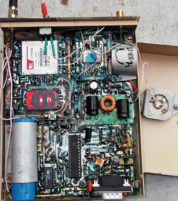
The GLONASS/GPS receiver board (see Fig. 9) is installed on the same racks as the modem. Its connections to the main board are made with wires. The charger board (see Fig. 11) is placed above the main board on six pieces of hard tinned copper wire with a diameter of 0,8 mm, through which the necessary electrical connections are also made. The holes on the main board into which these segments are soldered are indicated by dots inside. The lighthouse is assembled in a metal case measuring 152x120x35 mm. Its general view with the lid open is shown in Fig. 16. Inside the case, on racks 3...5 mm high, there is a printed circuit board of the beacon with a modem fixed on it, a GLONASS/GPS receiver and a charger. The modem and receiver antenna connectors are placed on the front wall of the case. The BM1 microphone is fixed on its removable cover.
System operation in navigation data transmission mode To transfer the coordinates of an object from the beacon to the base unit via the GSM network, the CSD protocol was chosen, in which the communication channel is occupied with digital information for the entire duration of the session, as in a normal voice connection. The transmission speed is 9600 baud. Today, the cost of such a transfer is usually close to the cost of a conversation of the same duration, i.e., relatively small, although more expensive than using the GPRS protocol. The undeniable advantage of CSD over GPRS is the absence of the need for a static IP address, which is quite expensive, and a third-party server for storing and broadcasting information, which reduces the reliability of the system as a whole. The duration of an information transmission session is not limited by anything, except for the cost of the services of a telecom operator. But the transfer of a significant amount of it (for example, to record the trace of an object's movement) is rarely required, since the main task of the system is to determine the current position of the object. To save battery power, the beacon is initially in a sleep state. In the base unit, when the SA1 switch is closed, the GPS modem and the Bluetooth module U1 are turned off, the DD1 microcontroller is in sleep mode. To enter the data transfer mode, press the SB2 button, after which the microcontroller wakes up, using the HA1 sound emitter, it gives a short beep, turns on the GSM modem and the Bluetooth module. LEDs HL3 and HL4 start flashing. While the modem is not registered on the network, the LED flashes are long with short pauses. After successful registration, the nature of its blinking changes: the flashes are shortened, and the pauses are significantly lengthened. The microcontroller sends a command to the modem to connect to the beacon in data transfer mode. When the connection is established, this is signaled by the blinking LED HL2. Establishing a connection in data transfer mode takes about 30 seconds (depending on the mobile operator), during this time it is necessary to establish communication between the Bluetooth module of the base unit and a terminal device, such as a computer. If a cell phone with the Navitel 3.5.0 navigation program is used as a terminal, Bluetooth connection will be established after the start of data transfer, and the navigation program will issue a voice message: "Communication with satellites is established." If a Bluetooth connection is established, the HL4 LED is always on. The HL2 LED flashes until the data transfer begins, after which it also lights up constantly. If there is no connection within a minute, the microcontroller will give the modem a hangup command, generate a short signal from the HA1 sound emitter and enter the waiting mode for a second request. There are two ways to exit the navigation data transfer mode: - press the SB2 button again, the beacon will return to its original state, and the GLONASS/GPS receiver in it will be turned off; - press the SB1 button, which will also reset the beacon, but the GLONASS/GPS receiver will continue to work in it. This is useful in poor satellite reception conditions where it takes a long time for the receiver to generate an almanac. When you exit the data transfer mode, the GSM modem and the Bluetooth module of the base unit will also be turned off. By closing the SA2 switch, you can reduce the time to re-enter the communication session due to the fact that the Bluetooth module and the GSM modem of the base unit will remain on all the time, but the average current consumed by the unit from the battery will increase. The data transfer mode is possible both when the protection is on and off. System operation in armed mode On the beacon, the armed mode is activated by a signal from the standard security alarm of the object or manually by the "secret" switch SA1 (see Fig. 13). To connect the beacon to the car's standard security alarm, its additional output is used. Usually this is a blue wire, the state of which in armed mode is set in accordance with the instructions for the alarm. In this case, it is necessary that when the object is armed, this wire is connected to the common wire ("ground") of the car and remains in this state until the alarm occurs or the alarm is turned off. After turning on the "secret" switch, the armed mode is set in about a minute. The beacon gives a short sound signal with a siren (HA1 in Fig. 13) about arming mode and makes a test call to a mobile phone or base unit, which should not be answered. In the armed mode, the state of the motion and rocking sensors, the operation of the standard alarm, the ignition on, the charge (availability) of the car battery are monitored. Any of the sensors, as well as the armed mode itself, can be excluded, and the parts that ensure their operation can be removed from the beacon, and no changes in the program of its microcontroller are required. Reception of alarm messages and transmission of requests about the current state of the object is possible with the help of both the base unit and a cell phone. Alarm voice messages are formed in the beacon from a set of phrases stored in the ISD5116 speech recording and playback chip (DD3 in Fig. 12). This feature is optional. Without the dD3 chip or if it malfunctions, a repeating sound signal will be given to the communication channel instead of a voice message. Messages about the current state of the object are issued by an incoming call to the beacon from the base unit or from a cell phone. The microphone present in the beacon makes it possible to listen to the sound environment at the protected facility. When any of the sensors is triggered, the beacon will dial the number of the base unit (or cell phone), report on the current situation and wait for an incoming call from the same subscriber to whom the message was sent for two minutes. If during this time the required call does not follow, the HA1 siren (see Fig. 13) will give 15 short beeps, after which the tracker will make a call to the reserve number. Outgoing calls will continue until the beacon receives an incoming call confirming receipt of the alarm. After that, the beacon will stop its calls, but will continue to periodically turn on the HA1 siren, while the triggered sensor remains in this state. The security mode will be exited only after the standard security alarm is turned off and the "secret" switch SA1 is opened (see Fig. 13). The phone numbers used must be pre-recorded in the format accepted in the network used, on the SIM card installed in the beacon's GSM modem, under the following names (in Latin letters): Mno - a subscriber who owns the main phone to which alarm messages will be sent and from which information about the current state of the object can be requested; Pqr - a service that informs via SMS about the current balance of the subscriber's account; T - subscriber whose incoming call serves as a command to request the balance of the beacon's SIM-card subscriber account; Wxy - a subscriber (usually a base unit), an incoming call from which activates the tracking mode for the object's coordinates. Some numbers may match, but they still need to be written to the SIM card under the corresponding names. All listed names and their corresponding numbers must be recorded on the card, even if the armed mode is not used. The SIM card installed in the beacon's GSM modem must contain the beacon's telephone number under the name Wxy. PIN prompts must be disabled on both cards. Microcontroller programs do not contain any information about phone numbers, but they check the caller's number and, if it differs from those on the SIM card, ignore the call. When receiving an incoming call from subscriber T, the beacon will form a request to subscriber Pqr and send the received response to subscriber T in the form of an SMS message. In response to an incoming call from an Mno subscriber, the beacon will report the current state of the protected object. Upon receiving a call from a Wxy subscriber in the format of a data transmission command, the beacon will turn on the tracking mode for the object's coordinates. Voice incoming call from the same subscriber does not include this mode. Setting up the base unit Before proceeding with the adjustment of the unit, it is necessary to carefully check its installation. Then, without connecting the power supply circuits to the GSM modem and the Bluetooth module and without installing the DD1 microcontroller in the panel, apply a voltage of 4,2 V to the block board from a separate source. For the first time, it should be fed through a milliammeter and a 0,5 ... 1 kOhm resistor connected in series with it. Only after making sure that there are no problems, you can apply power directly. Check for a voltage of +3,3 V at the output of the DA1 stabilizer. This must be done by temporarily connecting a load resistor with a resistance of 1 ... 5 kOhm to the output of the stabilizer. Follow the voltage changes at the sockets of the DD1 microcontroller panel depending on the positions of the switches and buttons. This procedure will avoid many of the difficulties associated with installation defects. Check the operation of the HL1 and HL2 LEDs by applying a voltage that turns on the LEDs to the corresponding sockets on the microcontroller panel. After making sure that everything is in order, install the microcontroller into the panel, into the memory of which the codes from the main.hex file, located in the "Base block" folder of the application, are loaded. After powering up module U1, close switch SA3. The HL4 LED should blink. Try to connect to your computer via Bluetooth. The first time you try to do this, you may need to enter the password 1234 at the request of the computer. If the connection is established, the HL4 LED should be on continuously. Connect the +4,2 V circuit of the main board to the corresponding output of the modem, and apply power to the modem. After switching on, the modem should remain in a passive state, and the current consumed by the unit should not increase by more than a few milliamps. Turning off the power again, install the SIM card in the modem, connect the antenna to it. Then turn on the power again. After that, the HL3 and HL4 LEDs should flash for a while. If the HL3 LED does not turn on, you need to check if the jumper S1 is in the modem in position 1-2. Upon completion of the procedures for switching on, checking the operability and registering the modem in the GSM network, the DD1 microcontroller program will turn off the modem and the Bluetooth module, and the microcontroller itself will put into sleep mode. Now you need to configure the modem by giving it a few AT commands. The sequence of actions is as follows: - press the SB1 button (in this case, the HL3 and HL4 LEDs should start flashing), the modem and the U1 module will be turned on, and their serial ports will be connected directly through the DD2 multiplexer; - establish a connection between the computer and the base unit via Bluetooth by opening the properties window of the created connection on the computer screen, find out the number of the virtual COM port created in the operating system; - run a terminal program on the computer, specifying this port number and setting the speed to 9600 baud with eight data bits without parity and one stop bit; - give the modem the AT command (in capital Latin letters without parameters) necessary for it to perform the automatic speed detection procedure. Like any other, it must end with a carriage return and a line feed. If the connection is established, the modem will reply OK. Further commands can be typed in letters of any case, and you cannot give the next one without waiting for the modem to confirm receipt and execute the previous one; - disable the echo mode with the ATE0 command; - use the AT&W command to save this setting in the non-volatile memory of the modem; - use the AT+IPR=9600 command to set a fixed communication speed of 9600 baud; - use the AT+CLIP=1 command to enable autodetection of incoming call number; - use the AT+CMGF=1 command to turn on the text mode. By default, the LED connected to the modem (HL3 according to the base unit scheme) in the absence of registration in the network gives flashes with a duration of 53 ms with pauses of 790 ms, and after its execution, the duration of pauses increases to 2990 ms. If desired, by using the AT+SLEDS=X,XZ commands, you can change the nature of the LED blinking. In each such command, the following parameters are set: mode number (1 - no registration, 2 - modem registered in the network, 3 - GRPS mode, not used in the system under consideration); Y - flash duration, ms; Z - pause duration, ms. For example, I use a sequence of commands: AT+SLEDS=1,700,53; AT+SLEDS=2,200,2990; AT+SLEDS=3,200,600. After completing the described operations, the modem is ready for operation. To check, you can use the ATD<number> command (only the numbers of the number are entered without angle brackets and spaces, if necessary they are preceded by the "+" sign and the country code) to make him call the specified number. The modem should answer OK, and the phone whose number was specified in the command should ring. If you dial the number of the SIM card installed in the modem of the base unit on the phone, in the window of the terminal program we get RING +CLIP: "<number>",145,""„"<name>",0 Here <number> is the phone number, the call of which was accepted by the modem; <name> - the name of the subscriber under which this number is recorded in the modem's SIM card. With the AT+CPBF="W" command, you can find out the numbers of all subscribers recorded in the SIM card of the modem, whose names begin with W. The modem should answer: The subscriber number named Wxy must be recorded on the SIM card for the normal operation of the system. To exit the modem test mode, press the SB1 button again. The HL3 and HL4 LEDs will turn off, and the base unit will go into standby mode. To check the operation of the base unit in armed mode, close the SA2 switch. LEDs HL3 and HL4 blink. When the modem is registered on the network, press the SB3 button. The device will dial the subscriber number Wxy. After making sure of this, give the end call command by pressing the same button again. Check the reception of an incoming call in armed mode by calling from the Wxy subscriber's phone to the SIM card number of the base unit. A repeating tone should sound in the speaker head BA1. Answer the call by pressing the SB3 button. To end the communication session, press the same button again. If for some reason the connection with the computer via Bluetooth does not work, the modem can be connected to the computer's COM port (physical or created using a USB-COM adapter) temporarily using a level converter, the diagram of which is shown in Fig. 17. At the same time, the DD1 microcontroller is removed from the panel and connected to the common wire of its sockets 12 and 13, associated with the address inputs A and B of the 74HC4052 switch. The RXD and TXD circuits of the converter are connected to sockets 7 and 8 of the microcontroller panel. Further, having launched a terminal program on the computer, all the procedures described above are performed.
Setting up a lighthouse Unlike the base unit, the GSM modem in the beacon must be in constant readiness for operation, so the modem's power does not turn off in the operating mode. But when performing adjustment work, it is necessary to be able to disconnect the battery. Switch SA1 is designed for this purpose. The recommendations for the first power supply are the same as for the base unit - apply power to all nodes in series, controlling the current consumption. The codes from the gps_main.hex file located in the "Lighthouse" folder of the application must be entered into the memory of the microcontroller installed in the beacon. Next, you need to configure the GSM modem, set up the GLONASS / GPS receiver and record voice messages in the DD3 chip (if used). GSM modem for the beacon can be configured by temporarily connecting it instead of a similar modem to the base unit board. In this case, the modem must be equipped with a SIM card intended for use in the beacon. The modem setup procedure differs from the one described earlier only in that at the end of it the AT+CSCLK=2 command must be given to enable the power saving mode. Now the modem will go into sleep mode after 5 seconds of inactivity. The modem will exit it when there is activity on the serial port lines, receiving an incoming call or receiving an SMS. The first command, after an idle time of more than 5 s, will only cause the modem to exit the power saving mode, and the second and subsequent ones will be executed. In the configured modem, before connecting it to the beacon board, it is necessary to move the jumper S1 from position 1-2 to position 2-3. The modem can be configured separately or by installing it into the beacon by connecting its TXD and RXD lines to the computer's COM port through the previously described adapter (Fig. 17). GLONASS/GPS receiver (node A3) is built on the SIM68V module, which by default provides navigation information at a rate of 115200 baud. It must be reduced to 9600 baud, since it is at this rate that information is transmitted over the GSM network. Unfortunately, the SIM68V module does not provide the ability to do this with simple commands, and the only way to change the speed is to load a new program into it. The utility for this and the program itself are located in the "SIM68V" folder of the appendix to the article. The operation does not require knowledge of the module software features and is performed in a few simple steps. To connect the receiver to the computer COM port, the level converter described above (Fig. 17) is used. Connect its lines TXD and RXD with the same lines of node A3. Next, do the following: - open the PowerFlash_Simcom.zip archives located in the "SIM68V" folder of the application (contains a computer program for reprogramming) and B03V11SIM68V_96.rar (contains information for writing to the module); - run the PowerFlash_ Simcom.exe program, press the "Connect" button, then the "Test" button. An error message will be displayed on the computer screen; - close the program, use a text editor to open the Powerflash.ini file and change the value of the ComSelect parameter in it from one to the number of the COM port to which the A3 node is connected via a level converter, then save the file; - after launching the program again, click on the "Download Agent" screen button, select the B03V11SI M68R_96_Al lInOne_DA_MT333 3_MP.BIN file, then click on the "Download ROM" screen button and select the B03V11SIM68R_96.bin file; - press the "Test" screen button. After the program is successfully downloaded to the receiver, a green circle will appear on the computer screen. The receiver will now output navigation information at 9600 baud. The only thing you should pay attention to is in the lines passed to them $GRPMC,181212,... the value of the current time (in this case, 18 hours 12 minutes 12 seconds UTC) should be followed by the letter A. The letter V in its place means that the data is invalid. This is usually due to unsatisfactory conditions for receiving signals from satellites (for example, indoors) or an insufficient number of satellites in the reception area. Tone Assembly Adjustment must be completed before installing the DD3 chip (ISD5116ED) on the beacon board. To do this, a configured modem must be connected to the beacon, and the programmed microcontroller of the beacon must be installed in its panel. Turning on the power of the beacon, make a call from your mobile phone to the number of the SIM card installed in the beacon. If a call is made from a number stored on the beacon's SIM card under the name Mno, in response to it (in the presence of a DD3 chip) a phrase should be heard characterizing the state of the beacon and the object on which it is installed, and when calling from a number that is not on SIM-card, - the phrase "Number not recognized". But if the DD3 chip is missing or when it is faulty, the beacon microcontroller generates and transmits a tone signal over the GSM channel. Trimmer resistor R29 is necessary to achieve its best reproduction by the phone from which the call was made. ISD5116ED chip programming (DD3) is performed after it is installed on the beacon board. It is necessary to enter into the memory of the microcircuit all the voice messages that the beacon should transmit in various situations. This is information about the events that have occurred and the current state of the sensors, as well as the state of the vehicle's battery. The ISD5116ED speech recording and playback chip is controlled using commands given on the I interface2C. To program it, you need to make a COM-I adapter2C, the diagram of which is shown in fig. 18, and load the codes from the i2c_rs2.hex file located in the "ISD232" folder of the application into the memory of the DD5116 microcontroller in it. This microcontroller is equipped with a hardware controller I2C. It converts the information coming from the computer's COM port to the XS1 connector into signals of this interface and transfers them to the ISD5116ED chip installed in the beacon. As shown in fig. 18, it must also be connected to the line output of the computer's audio card and connected to it a control UMZCH, which can be used as an active computer audio speaker. At the time of programming the DD3 chip, the beacon microcontroller (DD1) should be removed from the panel.
For recording into a microcircuit, it is necessary to prepare, using a microphone and a computer sound card, sound files containing the necessary phrases in any format accessible to a computer. It is convenient to use the Sound Forge 9.0 program, which allows you to change any parameters of sound fragments, merge them, cut out unnecessary sections. To reduce the amount of memory used, you should also remove the pauses at the beginning and end of each phrase. All phrases that must be written to the chip are listed in the table. It also indicates their approximate duration and the addresses from which they begin in the chip's memory. When recording, these addresses should be strictly observed, since it is by them that the program of the beacon microcontroller searches for the necessary sound fragments. If individual phrases turn out to be too long and it is not possible to put them in the allotted space, you will have to make changes to the program. The addresses at which the addresses of the beginning of phrases are located in it are available in the same table. When writing phrases to the chip, the following commands are used, which are sequences of bytes: EE 82 44 2F 83 00 C1 ED - recording configuration, audio signal input AnA IN (pin 18 of the microcircuit), AUX OUT output (pin 20); EE 82 24 26 83 59 D1 ED - playback configuration, audio output AUX OUT (pin 20); EC 91 HH LL ED - write command, HH - high byte of the address of the beginning of the recorded phrase, LL - its low byte; EC A9 HH LL ED - playback command, HH - high byte of the address of the beginning of the phrase being played, LL - its low byte; EB - command to stop recording or playback (in the latter case, it is not necessary, playback stops automatically when the end of the phrase is reached); EF - command to read the state of the microcircuit. These commands differ from those given in the IC's user manual because some of the bytes are used by the adapter's microcontroller. For example, upon receiving the EF byte, it forms and transmits over interface I2C real command to read the state of the chip. The terminal program that will issue commands should be configured to operate at 19200 baud with eight data bits without parity and one stop bit. Recording is done in the following order: - a recording configuration command is given, after which the sound file played by the computer can be listened to using the control UMZCH connected to the AUX OUT of the ISD5116ED chip; - a recording command is given with the starting address of the phrase and, with a minimum loss of time, playback of the desired phrase by the computer is started; - as soon as the phrase ends, the command to stop recording is given; - give a command to read the state of the ISD5116ED chip, to which a response of three bytes should be received. The second of them is the senior, and the third - the low byte of the address of the first after the recorded phrase free for writing the memory cell of the microcircuit. This address must not be greater than the starting address of the next phrase in the order specified in the table. Table
It is advisable to check the recording made by listening to it using the control UMZCH. To do this, you need to send a playback configuration command, then a playback command with the starting address of the phrase, and after its sounding, read the state of the microcircuit. Repeating the described cycle, all the necessary phrases are written into the microcircuit. Swing Sensor Assembly adjust by connecting the input of the oscilloscope to the output of the op-amp DA2. Trimmer R2 set this output to a high logic level. Next, specify the position of the resistor slider experimentally. When shaking the sensor (PA1 microammeter, the arrow of which is weighted with a piece of solder), the level at the output of the op-amp should change in time with the swing of the arrow. The final adjustment is made on the vehicle. The battery status control unit is adjusted by applying a voltage equal to the minimum allowable battery voltage (I have 5 V) to pin 1 of the XP11,2 connector of the beacon. Set the trimmer resistor R18 to a voltage of 1,05 V at the input RA2 of the microcontroller. The result is easy to check. Set the voltage to 5...1 V on pin 12 of the XP13 connector and, slowly reducing it, wait for a phone call with the message "Battery low". This should happen at a given minimum voltage. The remaining components of the lighthouse do not require adjustment work. Files of printed circuit boards in the Sprint Layout 6.0 format and all the programs necessary for operating and setting up the system can be downloaded from ftp://ftp.radio.ru/pub/2014/06/beacon.zip. Author: S. Polozov
Machine for thinning flowers in gardens
02.05.2024 Advanced Infrared Microscope
02.05.2024 Air trap for insects
01.05.2024
▪ Current behaves like a liquid ▪ Found a place with lifeless soil ▪ Biodegradable stent for children with respiratory diseases
▪ site section Chargers, accumulators, batteries. Article selection ▪ article Commodity science. Crib ▪ article Why is the Michelin Bibendum tire symbol white instead of black? Detailed answer ▪ article There are three in one backpack. Travel Tips
Home page | Library | Articles | Website map | Site Reviews
www.diagram.com.ua | ||||||||||||||||||||||||||||||||||||||||||||||||||||||||||||||||||||||||||||||||||||||||||||||||||||||||||||


 Leave your comment on this article: