|
|


 Arabic
 Bengali
 Chinese
 English
 French
 German
 Hebrew
 Hindi
Hindi Italian
 Japanese
 Korean
 Malay
Malay Polish
 Portuguese
 Spanish
 Turkish
 Ukrainian
 Vietnamese
|
ENCYCLOPEDIA OF RADIO ELECTRONICS AND ELECTRICAL ENGINEERING Electronic watchdog on the microcontroller. Encyclopedia of radio electronics and electrical engineering
Encyclopedia of radio electronics and electrical engineering / Safety and security The device offered to the attention of readers reacts to a break in electrical communication lines (loops) and notifies about it with light and sound signals. The watchdog is controlled by the PIC12F675 microcontroller, and the BTA140 triac connected to it by the MOC3062 optocoupler turns on the alarm. The electronic "watchman" described in the article is designed to protect the garden house. The purpose of installing such a device is to frighten an intruder when trying to enter the house and draw the attention of neighbors to the incident using sound and light alarms. The scheme of the device is shown in fig. 1. Its basis is the DD1 PIC12F675 microcontroller, the clock frequency of which is -4 MHz, set by the generator built into it. Security loops E4 and E3 are connected to lines GP3 and GP4 (pins 5 and 8, respectively) via terminal block XT1-XT2. Each of them can have one or more sensors connected in series (reed switches or mechanical buttons, which are shown as switches SA2-SA5) installed on doors and windows. In standby mode, the contacts of all sensors must be closed. Capacitors C4 and C5 protect the microcontroller inputs from impulse noise, which are possible on security loops.
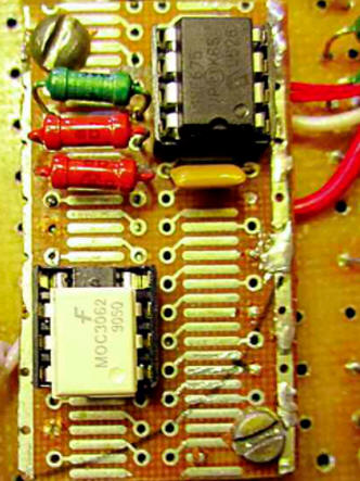
The executive part of the device controlled by the microcontroller is made on the U1 optotriac and the VS1 triac and is designed to connect incandescent signal lamps EL1, EL2 and sirens HA1, HA2. The indication necessary for the operation and debugging of the device is carried out by LEDs HL1 and HL2 of different glow colors connected to the lines GP1, GP5 (microcontroller outputs 6 and 2, respectively) through current-limiting resistors R4 and R5. The green LED HL1 turns on when you try to open the house. By its glow, the owner learns that someone in his absence tried to enter the house. The red LED HL2 indicates the activation of the alarm (pins 6 and 2 of the microcontroller change state simultaneously). This allows you to check the operation of the device without connecting signal sirens and lamps. The device is powered by AC 230 V 50 Hz. The 5 V voltage required for the operation of the microcontroller is created by a step-down transformer T1, a rectifier bridge VD1, an integrated voltage regulator DA1 and filter capacitors C1-C3. Fuse-link FU1 protects against emergency short circuits. The device works as follows. After the 230 V power supply is turned on and +5 V voltage is applied to the microcontroller, the microcontroller program starts, which configures its GP4 and GP3 lines for input, and the GP0, GP1 and GP5 lines for information output. The program implements the following algorithm of interaction with the host: 1. After the power is turned on, the owner has approximately 60 seconds to leave the house and close the door. 2. 1 minute after switching on, to check the serviceability of the devices, an alarm signal is turned on for 1 s (the lamp lights up, the siren sounds). The device becomes active. 3. The state of the sensors is checked at intervals of 1 s. When an open sensor is detected, after 10 s, an intermittent alarm is turned on (1 s on - 1 s off) and the HL1 LED lights up (as noted, the owner can determine from its state whether the alarm was turned on in his absence). A delay of 10 seconds for turning on the light and sound signals is necessary so that the returning owner, after opening the door, has time to turn off the mains power without triggering an alarm. 4. 3,5 minutes after switching on, the alarm is turned off, and the microcontroller checks the status of the sensors. If they are closed, the device goes into armed mode, while the HL1 LED continues to light. If an open sensor is detected, the device goes into host standby mode. The returned owner switches the device to its original state by turning off the power to the device. The source text of the microcontroller program and the HEX file are given in the Oxrana675.asm and Oxrana675.hex files, respectively. The same files set the required microcontroller configuration word (3F0CH). The details of the device are mounted on two fragments of breadboards made of foil fiberglass. On one of them (Fig. 2) a microcontroller, optocoupler, resistors R2, R3, R6 and capacitor C3 are installed, on the second - all other parts.
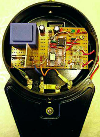
Possible replacement of the microcontroller PIC12F675 - PIC12F629 (without any modifications to the program), optocoupler MOC3062 - an optocoupler with a lower actuation current, for example, MOC3043 or MOC3063, but in this case, the resistor R1 must have a resistance of 680 ohms. We will replace the 2D906A diode bridge with another one suitable in terms of parameters (for example, KTs407A or DB107), and instead of a low-power integrated voltage regulator 78L05, you can use any other with an output voltage of 5 V (7805, KR142eH5a, etc.). Resistors and capacitors - small-sized any types. The step-down transformer used by the author has two secondary windings, of which only one is used. The current consumed from it is negligible, so you can use almost any other low-power transformer with a secondary winding of 8 ... 12 V. An ordinary household wall-mounted switch is used as the SA1 power switch. The design of the device as a whole may be different depending on the capabilities of the radio amateur. The author placed the boards in the case of an old household electricity meter (in recent years, these meters have been massively replaced by more accurate modern ones, so finding such a case will not be difficult). Two of the four powerful screw terminals in it are used to connect the wires connecting the device to the 230 V network, and the other two are wires coming from signal sirens and lamps (in the diagram, these contacts are designated as XT1-XT4). The wires of the loops are passed through the holes drilled in the case and connected to the board through the XT5-XT8 screw terminal block. LEDs HL1 and HL2 are installed on the circuit board inside the case (their glow is observed through the glass window in it). A view of the installation of the device is shown in fig. 3 (housing cover removed). The diode bridge VD1 is mounted on the reverse side of the large board and for this reason is not visible.
For loops, a telephone wire, for example, "noodles", can be used. The number of sensors connected in series is determined depending on the number of controlled windows and doors. The operation of the device was tested with loops up to 10 m long. If one loop is used for protection, a wire jumper is installed instead of the second. To scare an intruder and attract the attention of neighbors in the country, one of the lamps and one of the sirens are placed inside the room, and the rest are installed outside it, for example, on the roof. The author's version of the device is operated with two 40 W incandescent lamps and two SS-1 electromechanical sirens (the power consumed by each of them is 30 W). Triac VS1 is equipped with a small heat sink. However, if the power consumed by signaling devices does not exceed 150 ... 200 W, it can work without a heat sink. In addition, the activation of the burglar alarm happens rarely and for a short time, and the alarm itself is intermittent. Optosimistor U1 simply does not have time to heat up during operation. If necessary, the number of lamps and sirens can be increased, but the triac VS1 will have to be installed on a heat sink, selected taking into account the increase in power consumption. To work with the device, in addition to the above electromechanical sirens, more modern electronic signaling devices with a supply voltage of 230 V AC can be used. The disadvantage of the proposed device is its volatility: in the event of a power failure in the network, it ceases to perform its functions. To prevent this from happening, it can be connected to the network through an uninterruptible power supply (UPS). Any small power UPS designed for use with a computer will do. The operation of the device has been verified with the UPS IPpON Model Back Verso 600. Perhaps someone will decide to repeat the proposed security device with low-voltage signaling devices and a built-in backup battery. For such a design, the basis of the described device may be useful - a microcontroller with a program stored in its memory. The microcontroller program can be downloaded from ftp://ftp.radio.ru/pub/2015/02/ohrana675.zip. Author: E. Shenov
Machine for thinning flowers in gardens
02.05.2024 Advanced Infrared Microscope
02.05.2024 Air trap for insects
01.05.2024
▪ Quantum crystal to search for dark matter ▪ Dell Latitude 7212 Rugged Extreme Tablet Rugged Tablet ▪ Microchip MIC28514/5 buck converter ▪ External battery for Sanho HyperMac laptops
▪ site section Spectacular tricks and their clues. Article selection ▪ article by Lucian of Samosata. Famous aphorisms ▪ article Who is an osprey? Detailed answer ▪ Kindergarten teacher article. Standard instruction on labor protection ▪ article Transistors IRFR010 - IRFUC20. Encyclopedia of radio electronics and electrical engineering
Home page | Library | Articles | Website map | Site Reviews
www.diagram.com.ua |

 Leave your comment on this article: