|
|


 Arabic
 Bengali
 Chinese
 English
 French
 German
 Hebrew
 Hindi
Hindi Italian
 Japanese
 Korean
 Malay
Malay Polish
 Portuguese
 Spanish
 Turkish
 Ukrainian
 Vietnamese
|
ENCYCLOPEDIA OF RADIO ELECTRONICS AND ELECTRICAL ENGINEERING A simple LF and HF signal generator. Encyclopedia of radio electronics and electrical engineering
Encyclopedia of radio electronics and electrical engineering / Measuring technology A simple low and high frequency signal generator is designed to set up and test various devices and devices manufactured by radio amateurs. The low frequency generator generates a sinusoidal signal in the range from 26 Hz to 400 kHz, which is divided into five subranges (26...240, 200...1500 Hz: 1.3...10, 9...60, 56... 400 kHz). The maximum amplitude of the output signal is 2 V. The harmonic coefficient in the entire frequency range does not exceed 1,5%. The unevenness of the frequency response - no more than 3 dB. The built-in attenuator can attenuate the output signal by 20 and 40 dB. Smooth adjustment of the output signal amplitude is also provided with its control by the measuring device. The high frequency generator generates a sinusoidal signal in the range from 140 kHz to 12 MHz (subbands 140...340, 330...1000 kHz, 1...2,8,2,7...12 MHz). The high-frequency signal can be modulated in amplitude by the signal as from the internal low-frequency generator. as well as from the outside. The maximum amplitude of the output voltage is 0,2 V. The generator provides for smooth adjustment of the output voltage with amplitude control using a measuring device. The supply voltage of both generators is 12 V. The schematic diagram of the device is shown in fig. one.
The low frequency generator is based on a well known circuit. The frequency of the generated signal is changed by a double variable capacitor C2. The use of a block of capacitors of variable capacitance for generating low (30 ... 100 Hz) frequencies required a high input impedance of the generator amplifier. Therefore, the signal from the bridge is fed to a streaming follower on a field-effect transistor V1, and then to the input of a two-stage amplifier with direct connections (circuit A1). From the output of the microcircuit, the signal is fed to the output emitter follower on the transistor V3 and to the second diagonal of the bridge. From the resistor R16, the signal is fed to the output voltage divider (resistors R18-R22) and to the measuring device PU1. which controls the amplitude of the output signal. On the field-effect transistor V2, a cascade for stabilizing the amplitude of the output voltage is assembled, which works as follows. The output signal from the emitter of transistor V3 is rectified by diodes (V4, V5), and a constant voltage proportional to the amplitude of the output signal is applied to the gate of transistor V2, which plays the role of a variable resistance. If, for example, for some reason (either the ambient temperature or the supply voltage has changed, etc.) the amplitude of the output signal has increased, then the positive voltage supplied to the gate of the transistor V2 will also increase. The dynamic resistance of the transistor channel will also increase, which will lead to an increase in the negative feedback coefficient in the A1 microcircuit, the gain of the latter will decrease, which will lead to the restoration of the output signal amplitude. The connection between the source follower on the transistor V1 and the input of the A1 microcircuit is galvanic. This made it possible to exclude a large capacity transition capacitor and improve the phase characteristic of the generator. Trimmer resistor R12 set the optimal transmission ratio. The high frequency generator is made on three transistors V10-V12. The master oscillator is assembled on a transistor V11, connected according to a common base circuit. The cascade has no special features. The required range is selected by switching the loop coils. Inside the subband, the frequency is smoothly changed by a variable capacitor C14. The output stage is an emitter follower on the transistor V12. The signal is fed to it from a part of the turns of the loop coil, which further reduces the effect of the load on the generator frequency stability. From the resistor R35, the high-frequency voltage is supplied to the rectifier (diodes V13, V14), and the rectified voltage through the resistor R37 is supplied to the PUI measuring device, which controls the output signal voltage. On the transistor V10, connected according to the scheme with a common emitter, a modulating stage is assembled. Its load is the master oscillator. Thus, the master oscillator operates at an alternating supply voltage, therefore, the amplitude of the generator output voltage also changes, resulting in amplitude modulation. This construction of the generator made it possible to obtain a modulation depth from 0 to 70%. A low-frequency signal can be fed to the modulator from both an internal and an external generator. Both generators are powered by a rectifier with a stabilizer (Fig. 2), made according to a typical scheme.
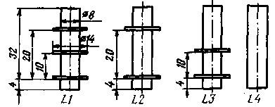
Both generators and the network power supply are made in the form of separate blocks installed in a common housing. The meter PU1 is also common to the generators. The high-frequency generator block is covered with a brass screen. The HF generator coils are wound on frames from the IF circuits of the Start-3 TV with carbonyl trimmers. On fig. 3 shows sketches of coil frames. Their winding data are given in the table. Coils L1, L2, L3 are wound in bulk, and the coil L4 - turn to turn. Transformer T1 is used ready-made from the Efir-M radiogram. In case of self-manufacturing of the transformer, it should be wound on the core Ш16Х24. The mains winding for a voltage of 220 V should contain 2580 turns of wire G1EV-2 0,15, the secondary - 208 turns of wire PEV-1 0,59.
The instrument scales are glued onto disks 90 mm in diameter, which, together with the pulleys of the vernier device, are fixed on the axes of capacitors of variable capacitance.
Instead of the KP103L transistor, you can use KP102E. This replacement may even slightly improve the parameters of the generator. The establishment of a low-frequency generator begins with the selection of a resistor R11. To do this, open the circuit R12, R13. A high-resistance voltmeter measures the voltage at the input of the A1 microcircuit (pin 4). Then, selecting the resistor R11 in the range from 300 ohms to 1,5 kOhm, they achieve the same voltage at the source of the transistor V1. If this cannot be done, the transistor V1 should be selected. (It may turn out that it will not be possible to select such a transistor, then you should untie the input of the microcircuit with the source of transistor V1 by direct current by including a 50 μF capacitor in the circuit break.) Having restored the open circuit, change the resistance of the resistor R12 so as to obtain at the output of the generator signal without distortion, controlling its shape on an oscilloscope. With a further decrease in the resistance of this resistor, a symmetrical clipping of the signal should occur. By setting the amplitude of the output signal to about 2 V and selecting the required resistance of the resistor R17 in the PU1 circuit, the establishment of the low-frequency generator is considered complete. The establishment of an RF generator begins with a modulating stage. Selecting resistor R23, a voltage of 10 V is set on the collector of transistor V6,2. Setting up a master oscillator consists in selecting resistor R31 in the positive feedback circuit. In this case, the shape of the output signal is controlled by the oscilloscope. Do this in the low frequency range. If the parameters of the oscilloscope allow, the test is also done on other frequency subranges. Then the resistor R37 is selected in the circuit of the measuring device. Having completed the adjustment of the blocks and having checked their operation in all subranges, they begin to select the elements of frequency-setting circuits and achieve the necessary overlap, after which the device is calibrated according to one of the methods repeatedly described in radio engineering literature and the Radio magazine. Author: V. Ugorov; Publication: N. Bolshakov, rf.atnn.ru
Machine for thinning flowers in gardens
02.05.2024 Advanced Infrared Microscope
02.05.2024 Air trap for insects
01.05.2024
▪ Parachute for the whole plane ▪ Brain implant for memory recovery ▪ Electricity storage in bricks ▪ Flood protection of the Maldives
▪ section of the website Electrotechnical materials. Article selection ▪ article Went into a room, ended up in another. Popular expression ▪ article Where do we get vitamins from? Detailed answer ▪ article Amphibian Mini-mokik. Personal transport ▪ article Types of biofuels. Wood. Encyclopedia of radio electronics and electrical engineering ▪ article Piercing with swords. Focus Secret
Home page | Library | Articles | Website map | Site Reviews
www.diagram.com.ua |


 Leave your comment on this article: